
More project photos (2)

The problem
Power-factor-correction capacitor banks quietly degrade. Metallized-film capacitors lose capacitance as their self-healing events accumulate, cans run hotter as losses rise, and one failed stage silently shifts the whole bank below its design kVAr — until the utility's power-factor penalty arrives to announce it. Most plants discover this at billing time because nobody measures individual stages. This project makes bank health visible: a monitoring add-on that self-tests each stage, estimates effective capacitance from the stage current it actually draws, watches temperature per stage, and presents degradation trends and watch/fail alerts on a dashboard. The student learns why banks fail and how the failure announces itself electrically, long before the bill does.
How it works
- The demo bank's six capacitor stages wire through contactors, with an ACS712-class current sensor and NTC thermistor on each stage.
- At the scheduled self-test (design 06:00 daily, or on demand), the controller switches each stage in alone while other loads are steady.
- The controller measures the stage's reactive current and the bus voltage, then estimates effective capacitance from C = I / (2πfV).
- Each estimate is compared with the buyer-calibrated nameplate baseline; the percentage deviation is logged and trended per stage.
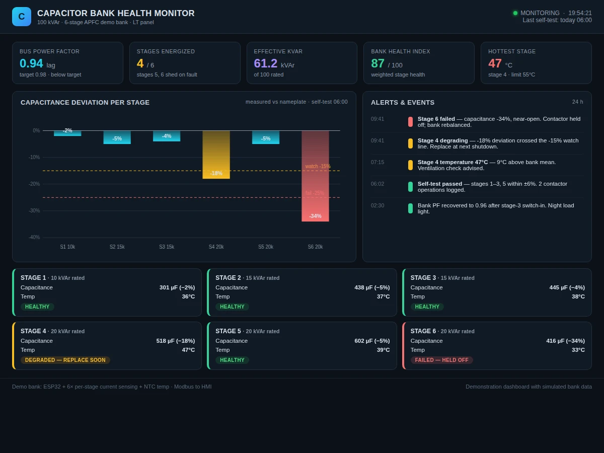
- Deviations past −15% raise watch alerts; past −25% the stage is marked failed, its contactor is held off, and the bank's effective kVAr is recomputed.
- Stage temperatures are sampled continuously; a stage hotter than the bank mean by the configured margin raises a thermal watch.
- All data publishes over MQTT to the dashboard, which renders the deviation chart, stage cards, health index and the 24-hour alert log.
Tech stack:
- ESP32 (controller)
- ACS712-class current sensors (per stage)
- NTC thermistors (per-stage temperature)
- Capacitor bank demo panel with contactors
- Modbus / MQTT telemetry
- Web dashboard (HTML, CSS, JavaScript)
- Arduino IDE (C/C++ firmware)
- 16x2 LCD with buzzer alerts
| Parameter | Value |
|---|---|
| Demo bank | 6 stages, 100 kVAr total (scaled demo cans) |
| Stage ratings (demo) | 10 / 15 / 15 / 20 / 20 / 20 kVAr |
| Capacitance method | C = I / (2πfV) during isolated self-test |
| Estimation accuracy | Design target within ±10% of LCR-meter check (buyer-verified) |
| Watch threshold | −15% deviation from calibrated baseline |
| Fail threshold | −25% deviation (contactor held off) |
| Temperature sensors | NTC per stage; alert on configured rise above bank mean |
| Self-test schedule | Daily 06:00 + on-demand (configurable) |
| Telemetry | MQTT to dashboard; local LCD + buzzer |
| Demo voltage | Low-voltage demo scale (not mains distribution) |
Project features
- [Per-stage capacitance self-test] Each stage is switched in alone against the known bus voltage; effective capacitance follows from the measured stage current (C = I / 2πfV) — no LCR meter needed.
- [Degradation trending] Every self-test result is logged and plotted per stage, so gradual capacitance loss shows as a downward trend weeks before any threshold trips.
- [Watch / fail thresholds] A −15% deviation raises a watch alert (plan replacement); −25% marks the stage failed and the controller holds its contactor off.
- [Per-stage temperature watch] NTC sensors track each can's temperature; a stage running hot relative to the bank mean is flagged as an early degradation signal.
- [Bank health index] A 0–100 score combines stage deviations, temperatures and failed-stage count into one at-a-glance number.
- [Automatic failed-stage hold-off] Failed stages are excluded from the switching sequence and the dashboard notes the rebalanced effective kVAr.
- [Event log] Self-test results, contactor operations and alerts are timestamped for the report's measured-data appendix.
- [Buyer-run calibration] The student calibrates the estimator against nameplate capacitance at commissioning, so thresholds rest on verified baseline values.
What is included
- Demo capacitor bank panel: 6 capacitor stages, contactors, per-stage current sensors and NTCs
- ESP32 firmware with self-test sequencer, capacitance estimator and hold-off logic
- Web dashboard source (deviation chart, stage cards, health index, alert log)
- Nameplate-baseline calibration procedure with LCR cross-check sheet
- Wiring diagram and contactor driving notes
- Project report PDF (capacitor ageing theory, reactive power, estimation method)
- PPT presentation for final review
- Viva Q&A preparation document (capacitance from current, self-healing, PF correction, contactor switching)
Limitations & prerequisites
- The estimator infers capacitance from current at line frequency; harmonic distortion on the bus affects the reading, which the report states openly.
- Estimation accuracy is a design target verified by the buyer against an LCR meter — the kit does not claim laboratory-grade capacitance measurement.
- The demo bank is low-voltage scale; a real LT/HT bank installation is the work of qualified personnel and is out of scope.
- This is a monitoring add-on, not certified protection equipment — it does not replace the bank's fuses, protection relays or maintenance schedule.
- Self-tests need a reasonably steady load during the test window; the firmware skips and retries if the bus is unstable.
Frequently Asked Questions
How can it measure capacitance without an LCR meter?
A capacitor's current at line frequency is I = 2πfVC, so with bus voltage known and the stage switched in alone, the measured current directly gives effective capacitance. It is an estimate, not a lab measurement, and the report says so.
Why do capacitor banks degrade?
Metallized-film capacitors self-heal through tiny internal breakdowns; each event removes a little electrode area, so capacitance drifts down and losses (and temperature) rise over years of service.
What happens when a stage fails?
Past −25% deviation the controller holds that stage's contactor off, recomputes the bank's effective kVAr, and raises a failed-stage alert — the bank keeps correcting with its remaining healthy stages.
How accurate is the health estimate?
The design target is within ±10% of an LCR-meter cross-check, and the buyer performs that cross-check at commissioning. The report documents the verified figure, not a claimed one.
Is this safe to build at home?
The demo bank is low-voltage scale and safe for a lab bench. Real distribution-voltage banks are never a home project — installation and maintenance belong to qualified personnel.
Is this project suitable for a final-year project?
Yes — for Electrical and Electronics programs. It applies AC circuit theory, sensing, embedded control and data trending to a genuine industrial maintenance problem. Suitable for B.E./B.Tech final-year projects in Electrical and Electronics.
Components & software requirements
- ESP32 (controller)
- ACS712-class current sensors (per stage)
- NTC thermistors (per-stage temperature)
- Capacitor bank demo panel with contactors
- Modbus / MQTT telemetry
- Web dashboard (HTML, CSS, JavaScript)
- Arduino IDE (C/C++ firmware)
- 16x2 LCD with buzzer alerts
Delivery information
Built-to-order project. Delivery timeline is shared after order confirmation based on current queue.
Support terms
Complete documentation, setup guide, and viva preparation included. Support for setup and explanation provided.