
More project photos (2)
The problem
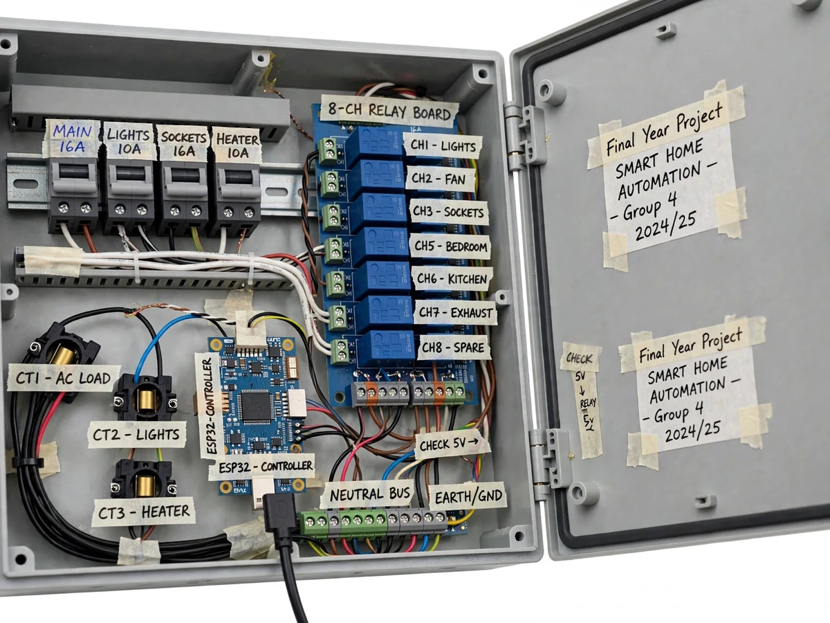
Home automation usually means switching lights from a phone, but without per-room energy measurement it is a remote control, not an energy tool. This project builds a proper automation panel: an MCB-protected enclosure housing an ESP32, an 8-channel relay board and per-room current sensors on a model home's room circuits. Each room can be switched from physical panel switches, the dashboard, or schedules, and the dashboard shows live per-room power, 24-hour load curves and daily energy totals. The honest engineering is in the measurement: current transformers per room, RMS computation in firmware, and a calibration procedure against a reference meter. Demonstrated on a model home load bank with lamp and fan loads, it shows both control and accountability.
How it works
- Room circuits on the model home load bank are wired through the panel's MCBs, current transformers and relay contacts.
- The ESP32 samples each CT, computes RMS current, multiplies by the configured voltage to get per-room power, and accumulates energy.
- Every 5 seconds (design target) the ESP32 publishes room states, power and energy over Wi-Fi via MQTT.
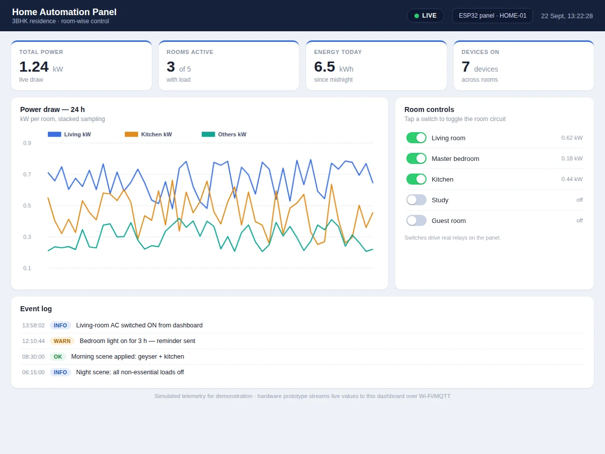
- The dashboard renders room toggle cards with live power, the 24-hour per-room curves and the daily energy totals.
- Switching from a panel switch, dashboard toggle or schedule drives the corresponding relay; firmware confirms the state change back to the dashboard.
- Schedules fire at configured times — e.g. the evening scene brings on living-room and kitchen circuits, night mode drops the rest.
- The buyer calibrates each CT channel against a reference meter using the documented procedure.
Tech stack:
- ESP32 development board
- 8-channel relay board (10 A)
- Current transformers per room (SCT-013 class)
- MCBs + enclosure + terminal blocks
- MQTT broker + web dashboard
- Arduino IDE (C/C++ firmware)
- Model home load bank (lamps, fans)
- Reference energy meter (calibration)
| Parameter | Value |
|---|---|
| Controller | ESP32, Wi-Fi MQTT telemetry (JSON payloads) |
| Channels | 8 relay channels, 10 A rated (resistive demo loads) |
| Sensing | Per-room CT, RMS current in firmware; approximately +/-3% typical (expected) |
| Update rate | 5-second design-target telemetry; switching immediate |
| Dashboard | Room toggles, per-room power, 24-hour curves, energy totals, schedules |
| Protection | MCBs per circuit group, earth bonding, manual override switches |
| Power | 230 V AC demo loads via panel; control at 5 V DC |
| Safety | Mains wiring in enclosed panel; supervised assembly per build guide |
Project features
- [Relay-switched room circuits] Eight relay channels switch room circuits from panel switches, the dashboard or schedules, with manual override always available.
- [Per-room current sensing] A current transformer per room feeds RMS computation in firmware, so every room's power is measured, not estimated.
- [Room-wise load dashboard] Live per-room power, 24-hour load curves per room, total power and daily energy totals — the energy picture behind the switches.
- [Scheduling and scenes] Time schedules (morning/evening scenes) and a night mode that drops non-essential loads are configured from the dashboard.
- [Energy analytics] Daily and weekly energy totals per room identify the biggest consumers; the report uses them for a savings discussion.
- [MQTT telemetry] The ESP32 publishes room states and power readings as JSON over Wi-Fi via MQTT with a design-target 5-second update interval.
- [MCB-protected panel] The demonstration panel includes MCBs per circuit group, proper terminal blocks and earth bonding — panel-building practice, not a breadboard.
What is included
- Working automation panel (enclosure, MCBs, relays, CTs, ESP32) with model home load bank
- Complete firmware source (RMS metering, relay control, schedules, MQTT)
- Live web dashboard (room control, load graphs, energy analytics) demonstrated with the panel
- Panel wiring diagram and single-line layout
- CT calibration procedure against a reference meter
- Component list with ratings
- Project report PDF (home automation background, metering principles, panel design, methodology)
- PPT presentation for final review
- Viva Q&A preparation document (relays, CTs, RMS, MQTT, scheduling)
- Setup and demonstration guide
Limitations & prerequisites
- Demonstrated with resistive/inductive demo loads (lamps, fans) on a model home — it is a panel and metering demonstration, not a certified domestic installation.
- Per-room power is computed as V_rms x I_rms with a configured voltage; true power-factor measurement per room is listed as future scope.
- Current sensing is approximately +/-3% (expected) after calibration — enough for energy awareness, not for billing.
- Mains wiring is enclosed in the panel and assembled under supervision per the build guide; students do not work on live conductors.
- Cloud history needs Wi-Fi; local switching and metering continue without it.
Frequently Asked Questions
How is per-room power measured?
Each room circuit passes through a current transformer. The ESP32 samples the CT waveform, computes RMS current in firmware and multiplies by the configured mains voltage. Channels are calibrated against a reference meter with the documented procedure.
What can be controlled from the dashboard?
All eight relay channels — room toggles with live power readouts, plus time schedules and scenes like evening and night mode. Physical panel switches always override, so control never depends on the network.
Does it measure power factor?
The base build computes apparent power per room (V x I). True per-room power-factor measurement is documented as future scope in the report — the hardware provision is there.
How accurate is the energy tracking?
Approximately +/-3% per channel after calibration (expected) — solid for energy awareness and the savings discussion in the report, but not billing-grade.
Is the panel safe?
The demo panel uses MCBs per circuit group, proper terminal blocks and earth bonding inside an enclosure, and mains assembly is supervised per the build guide. It demonstrates panel-building practice on demo loads.
Is this project suitable for a final-year project?
Yes — for Electrical Engineering programs. It combines panel building, CT-based metering, relay control, MQTT telemetry and energy analytics, all strong viva material. Suitable for B.E./B.Tech final-year projects in Electrical Engineering.
Components & software requirements
- ESP32 development board
- 8-channel relay board (10 A)
- Current transformers per room (SCT-013 class)
- MCBs + enclosure + terminal blocks
- MQTT broker + web dashboard
- Arduino IDE (C/C++ firmware)
- Model home load bank (lamps, fans)
- Reference energy meter (calibration)
Delivery information
Built-to-order project. Delivery timeline is shared after order confirmation based on current queue.
Support terms
Complete documentation, setup guide, and viva preparation included. Support for setup and explanation provided.