
More project photos (2)
The problem
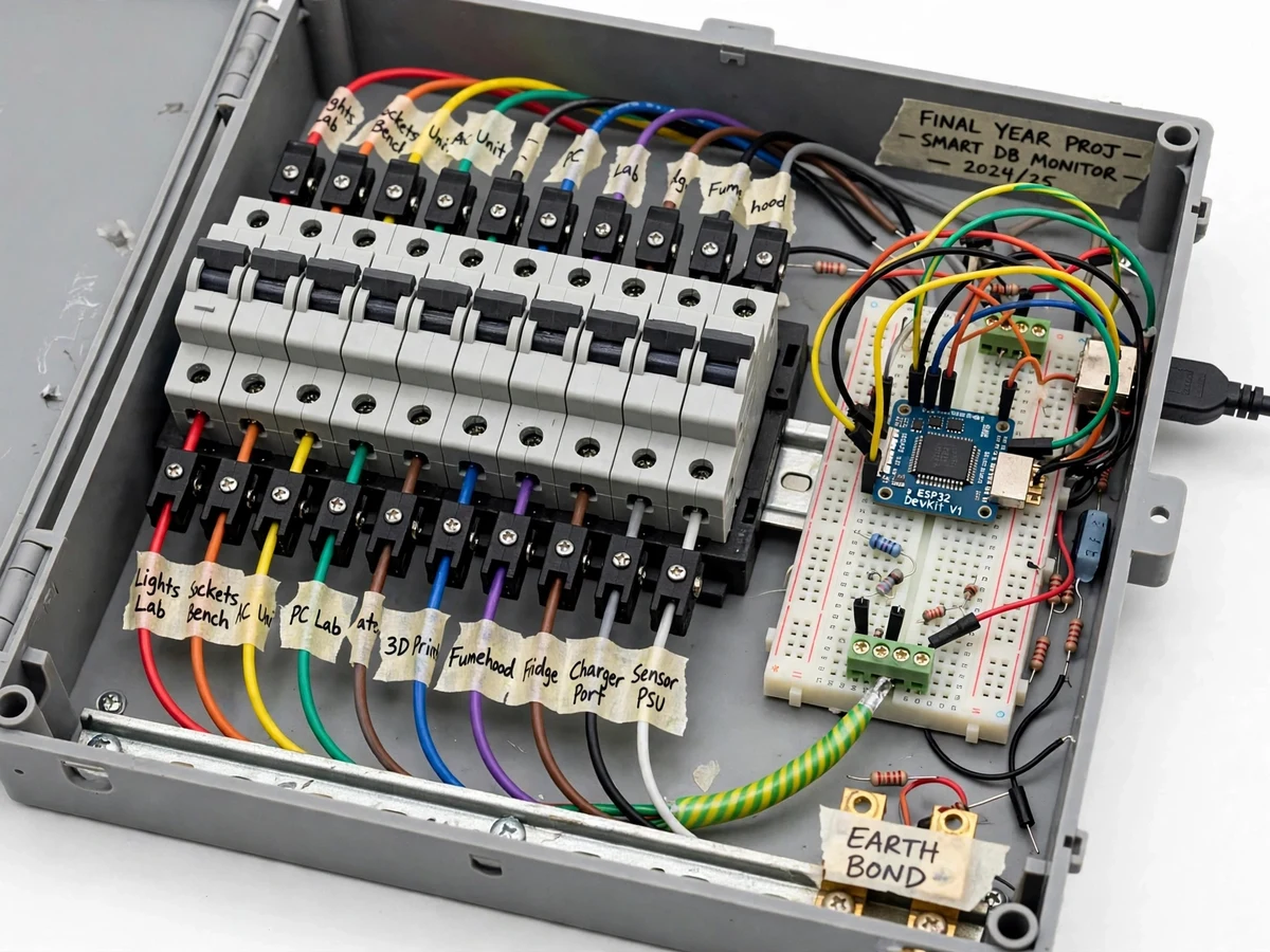
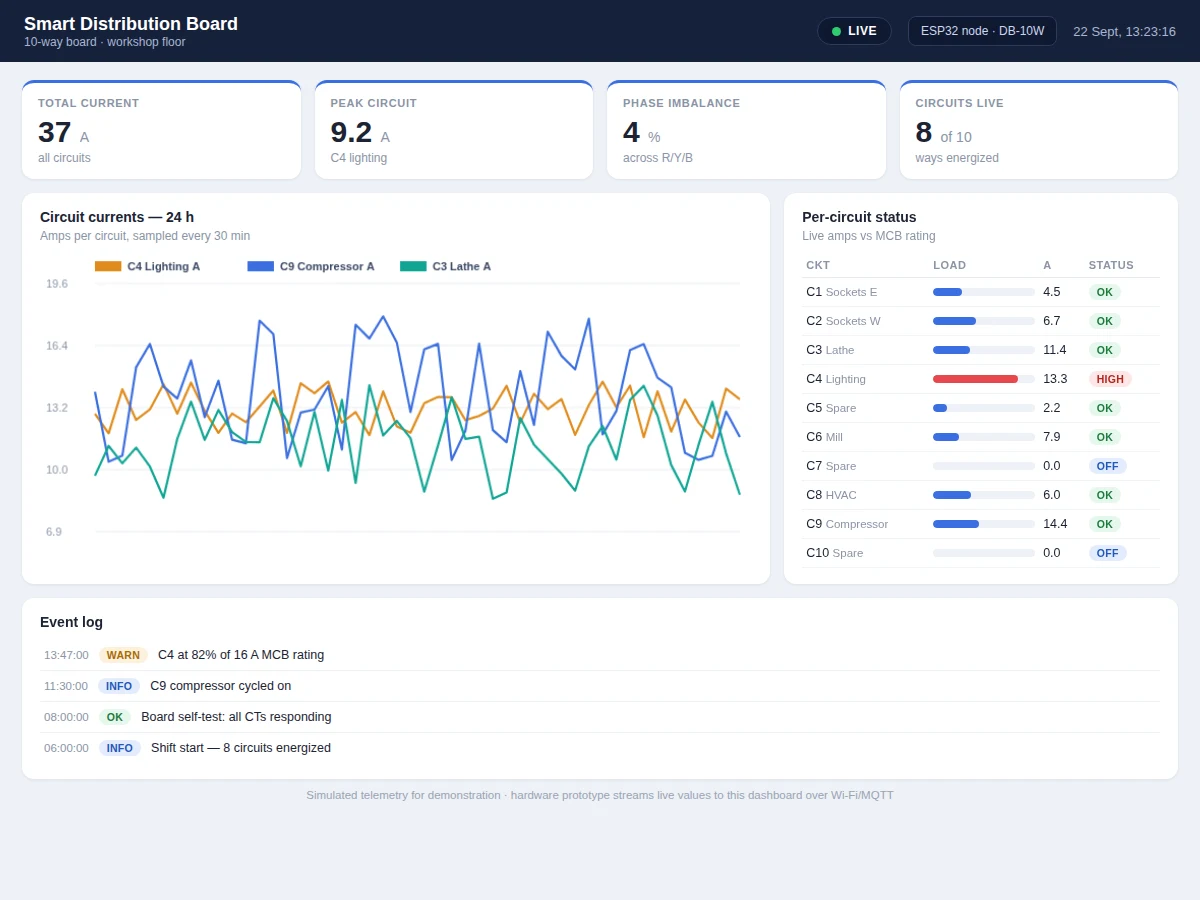
When a workshop MCB trips, the usual response is to reset it and hope — nobody knows which circuit was actually overloaded, or whether the board is balanced across phases. This project turns a standard 10-way distribution board into an instrumented one: a clamp CT on every outgoing circuit feeds an ESP32 through a multi-channel conditioning stage. Firmware computes per-circuit RMS current, compares each against its MCB rating, watches phase balance, and publishes everything over Wi-Fi via MQTT. The dashboard shows a live circuit table with current-vs-rating bars, total board load, a phase-balance readout and 24-hour per-circuit profiles, with alerts when any circuit crosses 80% of its breaker rating. Built with proper panel practice — MCBs, terminal blocks, earth bonding — it demonstrates both instrumentation and protection awareness.
How it works
- Each outgoing circuit of the 10-way board passes through its own clamp CT, wired to the multi-channel conditioning stage and ESP32.
- Firmware samples all channels, computes RMS current per circuit, totals the board load and evaluates the phase-balance math.
- Every 5 seconds (design target) the ESP32 publishes the 10 currents, totals and status flags as JSON over Wi-Fi via MQTT.
- The dashboard renders the circuit table with current-vs-rating bars, the board total and the phase-balance readout.
- When any circuit crosses 80% of its MCB rating, an alert is raised with the circuit ID, current and rating.
- 24-hour per-circuit profiles are stored for the load-analysis view and the report.
- The buyer calibrates each CT channel against a clamp reference meter with the documented procedure.
Tech stack:
- ESP32 development board
- 10-way distribution board + MCBs
- Clamp CTs x10 (SCT-013 class)
- Multi-channel CT conditioning stage
- MQTT broker + web dashboard
- Arduino IDE (C/C++ firmware)
- Workshop load bank (demo circuits)
- Clamp reference meter (calibration)
| Parameter | Value |
|---|---|
| Controller | ESP32, Wi-Fi MQTT telemetry (JSON payloads) |
| Circuits | 10 outgoing ways, one CT each |
| Sensing | Clamp CT per circuit; approximately +/-3% typical (expected) |
| Alert threshold | 80% of MCB rating per circuit (configurable) |
| Reporting | 5-second design-target interval; MQTT reconnect with backoff |
| Dashboard | Circuit table, rating bars, board total, phase balance, 24-hour profiles |
| Protection | MCBs per circuit, earth bonding, enclosed panel |
| Power | 230 V AC demo circuits; sensing isolated via CTs |
Project features
- [Per-circuit CT monitoring] A clamp current transformer on each of the 10 outgoing circuits gives true per-circuit current — the missing visibility in ordinary boards.
- [Overload pre-alerts] Each circuit is compared against its MCB rating; crossing 80% raises a dashboard alert before the breaker ever trips.
- [Live circuit dashboard] Circuit table with current-vs-rating bars, total board load, phase-balance readout and per-circuit 24-hour profiles.
- [Phase-balance watch] The dashboard computes imbalance across the three phases and flags persistent imbalance for the report's analysis.
- [MQTT telemetry] The ESP32 publishes all 10 channels as JSON over Wi-Fi via MQTT with a design-target 5-second interval.
- [Proper panel build] MCBs, terminal blocks, earth bonding and cable management in an enclosure — distribution-board practice, not a breadboard.
- [Trip forensics] If a breaker trips, the dashboard's history shows exactly which circuit was climbing and when — the story behind the trip.
What is included
- Working instrumented 10-way distribution board (MCBs, 10 CTs, ESP32) with load bank
- Complete firmware source (multi-channel RMS, balance math, MQTT)
- Live web dashboard (circuit table, profiles, alerts) demonstrated with the board
- Panel wiring diagram and single-line layout
- Per-channel CT calibration procedure against a clamp reference
- Component list with ratings
- Project report PDF (distribution background, CT metering, protection coordination, methodology)
- PPT presentation for final review
- Viva Q&A preparation document (CTs, MCB coordination, phase balance, MQTT)
- Setup and demonstration guide
Limitations & prerequisites
- Demonstrated with workshop demo loads — it is an instrumented board demonstration, not a certified installation for a real premises.
- Per-circuit accuracy is approximately +/-3% (expected) after calibration — enough for overload trending, not for sub-billing.
- The dashboard alerts on overload conditions; it does not replace the MCB's protection function, which the report states explicitly.
- Phase-balance math assumes the configured phase assignment per circuit; wrong assignment reads as imbalance.
- Mains assembly is enclosed and supervised per the build guide; students do not work on live conductors.
Frequently Asked Questions
What does per-circuit monitoring add over a normal board?
Visibility: you see each circuit's live current against its breaker rating, so overloads are predicted instead of discovered by tripping. The dashboard's history also explains past trips — which circuit was climbing and when.
How are the currents measured?
A clamp CT on each outgoing circuit — non-invasive and isolated. The ESP32 computes RMS per channel through a multi-channel conditioning stage, calibrated against a clamp reference meter.
Does it replace the MCBs?
No — and the report is explicit about this. The MCBs remain the protection; the monitoring predicts overloads and documents them. Protection and instrumentation are complementary, not substitutes.
What is the 80% alert?
A configurable pre-alarm: when a circuit's current crosses 80% of its MCB rating, the dashboard flags it so loads can be redistributed before a trip. The threshold is adjustable per circuit.
How accurate is it?
Approximately +/-3% per channel after calibration (expected) — solid for overload trending and the phase-balance analysis, not sub-billing grade.
Is this project suitable for a final-year project?
Yes — for Electrical Engineering programs. It combines distribution-board building, multi-channel CT metering, protection awareness and MQTT telemetry, all strong viva material. Suitable for B.E./B.Tech final-year projects in Electrical Engineering.
Components & software requirements
- ESP32 development board
- 10-way distribution board + MCBs
- Clamp CTs x10 (SCT-013 class)
- Multi-channel CT conditioning stage
- MQTT broker + web dashboard
- Arduino IDE (C/C++ firmware)
- Workshop load bank (demo circuits)
- Clamp reference meter (calibration)
Delivery information
Built-to-order project. Delivery timeline is shared after order confirmation based on current queue.
Support terms
Complete documentation, setup guide, and viva preparation included. Support for setup and explanation provided.