
More project photos (2)
The problem
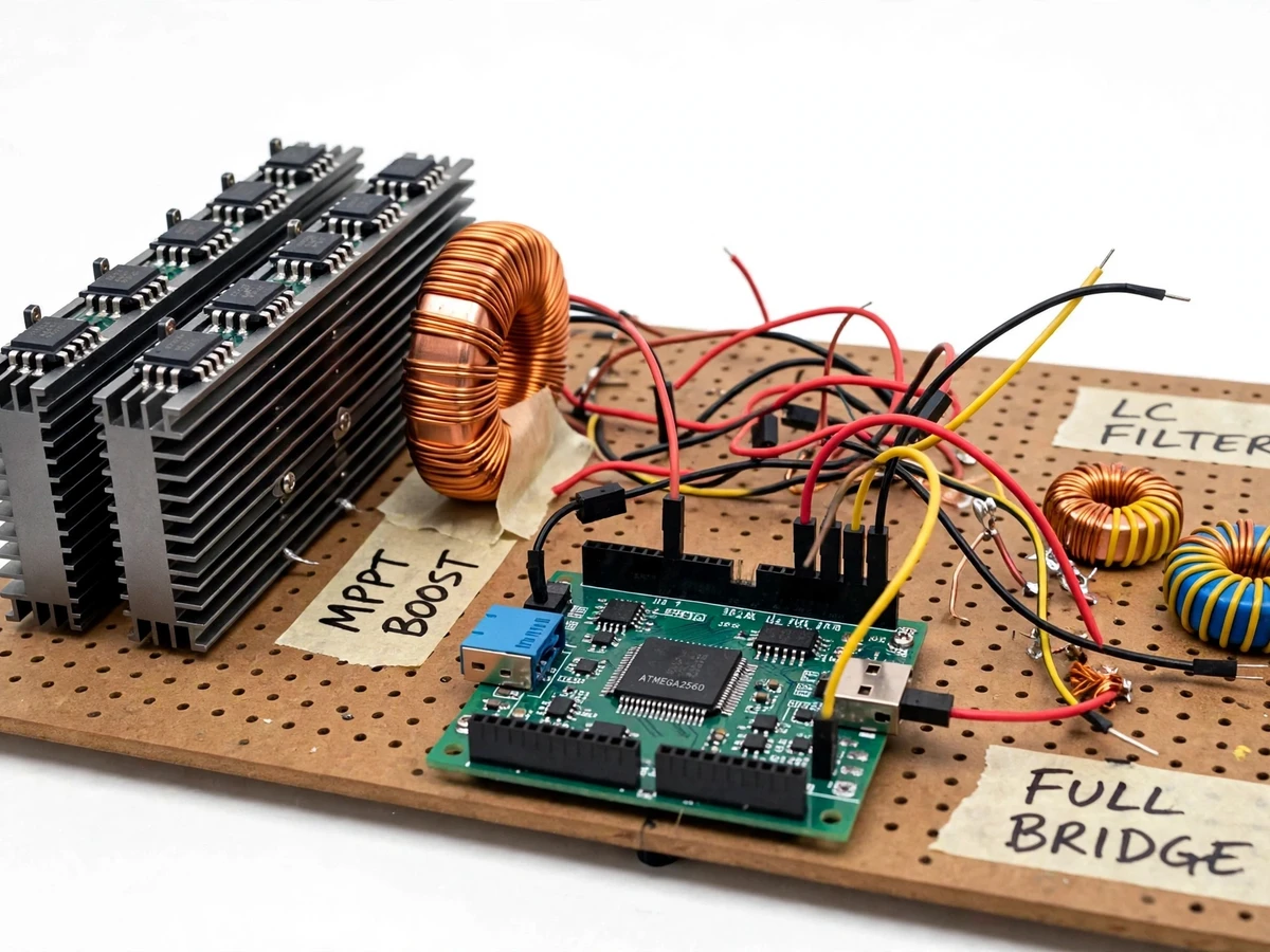
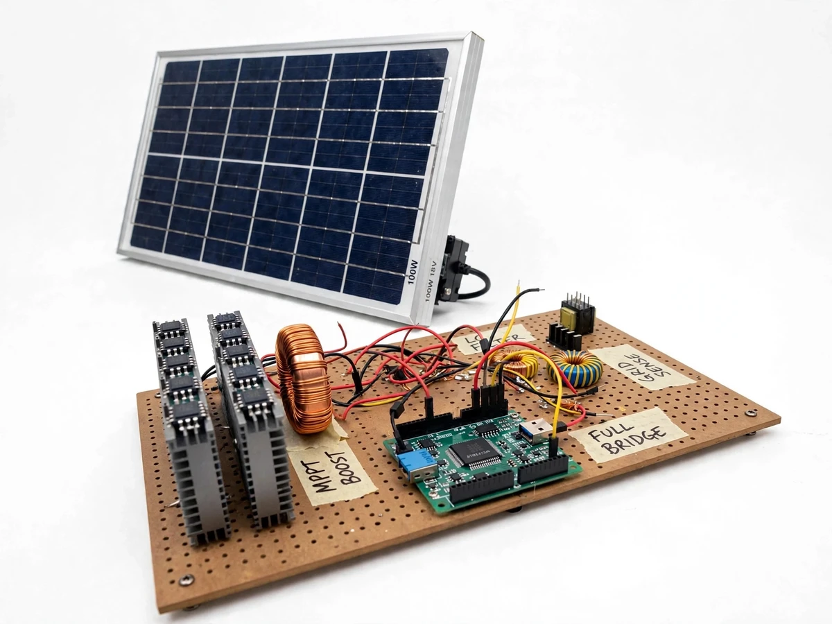
Solar panels generate direct current, but the grid — and most loads — run on 230 V, 50 Hz alternating current. Conventional string inverters handle this conversion centrally: one box for an entire rooftop, a single point of failure, and a cost that keeps small installations on the sidelines. Microinverters flip the architecture — one small inverter per panel, each with its own maximum power point tracking — so a shaded or dusty panel never drags the whole array down, and a system can start with a single panel and grow. This project builds that architecture as a student-grade power-electronics system: a single 100–200 Wp panel feeds a DC-DC boost stage with perturb-and-observe MPPT, a MOSFET full bridge synthesizes 50 Hz AC with sinusoidal PWM, an LC filter cleans the waveform, and a software phase-locked loop synchronizes the output to the 230 V/50 Hz reference before the output contactor closes. Over/under-voltage and over/under-frequency trips provide anti-islanding protection, and a documented procedure covers the supervised path to real-mains integration.
100-200 Wp panel delivering about 17-22 V DC at maximum power.
Follow the working sequence
How it works
- The 100–200 Wp panel's DC output (~17–22 V at maximum power) enters the boost stage, where the Arduino runs perturb-and-observe MPPT: it nudges the boost duty cycle and keeps the direction that raises panel power.
- The boost converter charges the DC-link capacitor bank to ~330 V DC (design target) — high enough for the full bridge to synthesize a 230 V RMS sine, since 230 V RMS peaks at about 325 V.
- The Arduino generates SPWM in firmware: a 50 Hz sine reference is compared against a ~16–20 kHz triangular carrier (design target), and the resulting gate pulses drive the four IRFP460N MOSFETs through the two IR2110 drivers.
- The LC filter removes the switching-frequency carrier from the bridge output, delivering a clean 50 Hz sine to the output contactor; the contactor stays open until synchronization is confirmed.
- Meanwhile, the reference supply's voltage is stepped down by the isolation transformer, squared through the PC817 optocoupler, and its zero crossings feed a software PLL that locks the SPWM reference's phase and frequency to the reference.
- When the PLL reports lock — frequency within ±0.5 Hz and phase error within ±5° (design targets) — the controller closes the contactor and the inverter feeds the resistive test load in phase with the reference, while MPPT keeps maximizing panel power.
- Anti-islanding runs on every cycle: if the reference voltage or frequency leaves the trip window, the contactor opens within the designed trip time and only recloses after the reference has been stable for the configured hold time.
Tech stack:
- Arduino Mega 2560 (ATmega2560 @ 16 MHz; 10-bit ADC for V/I sensing; hardware timers for SPWM)
- 100–200 Wp solar PV panel, 36-cell class (Vmp ~17–22 V, Imp up to ~11 A)
- Boost DC-DC stage: ferrite-core inductor, fast-recovery diode, DC-link capacitor bank
- Full bridge: 4 × IRFP460N MOSFET (500 V / 20 A per datasheet) on individual heatsinks
- 2 × IR2110 high/low-side gate drivers (500 V, 2 A source/sink per datasheet)
- LC output filter: ~3.3 mH series inductor, ~2.2 µF film capacitor (design values)
- Grid sensing: small isolation transformer + PC817 optocoupler zero-crossing detector
- Output contactor + fused DC input for protection
- Arduino (C++) firmware: P&O MPPT, SPWM, software PLL, anti-islanding state machine
- ESP32 telemetry logging (optional configurable extension, not part of the base build)
| Parameter | Value |
|---|---|
| PV input | 100–200 Wp, 36-cell class; Vmp ~17–22 V, Imp up to ~11 A (design) |
| DC link | ~330 V DC (design target) |
| AC output | 230 V RMS / 50 Hz single-phase, 200 W rated into resistive test load (design targets) |
| SPWM carrier | ~16–20 kHz (design target) |
| Power stage | 4 × IRFP460N (500 V / 20 A per datasheet); 2 × IR2110 gate drivers (500 V / 2 A per datasheet) |
| Output filter | L ~3.3 mH series, C ~2.2 µF film (design values) |
| MPPT | Perturb-and-observe, ~200 ms perturb interval (design target) |
| Grid sync | Software PLL; lock window ±0.5 Hz / ±5° phase (design targets); zero-crossing via PC817 optocoupler |
| Anti-islanding | Trip on 207–253 V or 48–52 Hz excursion (design target windows); reclose after stable hold time |
| Output THD | Under 5% at rated load (design target; verified by the buyer's own measurement) |
Project features
- [Perturb-and-observe MPPT] The boost-stage duty cycle is nudged every ~200 ms (design target) and panel power is compared before and after, so the operating point climbs to the maximum power point and holds it as sunlight changes — implemented in Arduino firmware.
- [Boost DC-DC stage] Raises the panel voltage (Vmp ~17–22 V) to a ~330 V DC link (design target), high enough for the full bridge to synthesize a 230 V RMS sine; built with a ferrite-core inductor and fast-recovery diode.
- [SPWM full-bridge inverter] Four IRFP460N MOSFETs (500 V / 20 A per datasheet) on individual heatsinks, driven by two IR2110 gate drivers (500 V / 2 A per datasheet), switch a 50 Hz reference sine against a ~16–20 kHz carrier (design target).
- [LC output filter] A series inductor plus film capacitor strip the switching carrier from the PWM waveform, leaving a 50 Hz sine for the test load; component values are documented design values.
- [PLL grid synchronization] Zero-crossings of the reference supply are sensed through a small isolation transformer and PC817 optocoupler, and a software phase-locked loop aligns the SPWM reference phase and frequency before the output contactor is allowed to close.
- [Anti-islanding protection] The controller opens the output contactor when the reference voltage or frequency leaves its trip window (design targets: 207–253 V, 48–52 Hz) and reconnects only after the reference stays stable for a configurable hold time.
- [Simulated-grid validation] The build is validated into a resistive test load against a variable AC source acting as the simulated grid, so every claim on this page is demonstrable in a college lab.
- [Buyer-run verification procedures] An MPPT verification routine (I-V sweep on the buyer's own panel) and a sync/trip test checklist ship with the build, so measured figures in the report come from the student's own hardware, never invented.
What is included
- Assembled prototype: boost stage, MOSFET full bridge on heatsinks, LC filter, Arduino Mega control board, sensing board, output contactor, resistive test load bank
- Arduino firmware (C++): P&O MPPT loop, SPWM generator, software PLL, anti-islanding state machine — commented for the viva
- Power-stage schematic and wiring diagram (single-line + component-level)
- 100–200 Wp PV test panel sized to the prototype
- MPPT verification procedure (I-V sweep routine the buyer runs on their own panel)
- Sync and trip test checklist for the simulated-grid setup
- Mains-integration safety procedure (licensed-electrician supervised connection checklist)
- Calibration guide for the voltage and current sense channels
- Project report PDF (10 sections), PPT presentation, viva Q&A document
Advantages
- Complete power-electronics chain: a 100–200 Wp panel feeds a boost stage raising panel voltage (Vmp ~17–22 V) to a ~330 V DC link, then a four-MOSFET (IRFP460N) SPWM full bridge with IR2110 gate drivers synthesizes 50 Hz AC through an LC filter for a clean sine.
- Perturb-and-observe MPPT implemented in Arduino firmware: the boost duty cycle is nudged every ~200 ms and the operating point climbs to the maximum power point as sunlight changes.
- Software PLL grid synchronization: reference zero-crossings sensed through an isolation transformer and PC817 optocoupler align the SPWM reference phase and frequency (lock window ±0.5 Hz / ±5°) before the output contactor is allowed to close.
- Anti-islanding protection: the controller opens the output contactor when the reference voltage or frequency leaves its trip window (207–253 V, 48–52 Hz design targets) and reconnects only after the reference stays stable for a hold time.
- Lab-validated by design: the build is tested against a variable AC source acting as a simulated grid into a resistive test load, with buyer-run MPPT verification (I-V sweep on the buyer's own panel) and sync/trip test checklists — measured figures come from the student's own hardware, never invented.
Disadvantages
- Validated on a simulated grid only — real-mains connection requires a licensed electrician and the utility's interconnection approval; net-metering and billing hardware are NOT part of the build.
- Single-panel 200 W class: a whole-rooftop array needs a redesigned power stage with larger MOSFETs, magnetics and heatsinks.
- Efficiency, THD and trip-time figures are design targets, never measured claims; the included procedures let the buyer measure them on their own build and report honestly.
- No battery or charge-controller stage — this is a daytime grid-feed build — and the firmware trip logic is prototype-grade protection, not certified grid-code compliance.
Limitations & prerequisites
- The build is validated on a variable AC source as a simulated grid in the lab; connecting to real mains requires a licensed electrician and compliance with the local utility's interconnection rules — net-metering and billing hardware are NOT part of this build.
- Rated for the 200 W / single-panel class; a whole-rooftop array needs a redesigned power stage with larger MOSFETs, magnetics and heatsinks.
- Efficiency, THD and trip-time figures are design targets, never measured claims; the included procedures let the buyer measure them on their own build and report honestly.
- No battery or charge-controller stage — this is a daytime grid-feed build; night-time or backup operation is future scope.
- The firmware trip logic is prototype-grade protection, not certified grid-code compliance — stated as an educational build.
- Thermal design assumes the specified heatsinks with natural convection at 200 W; sustained overload or a hot enclosure needs derating.
Frequently Asked Questions
How does the perturb-and-observe MPPT work?
The Arduino measures panel voltage and current, computes power, then nudges the boost converter's duty cycle slightly. If power rose, it keeps nudging the same way; if power fell, it reverses. Repeating this every ~200 ms (design target) climbs the panel's I-V curve to its maximum power point and tracks it as sunlight changes.
How does it synchronize with the grid?
The reference supply is stepped down by a small isolation transformer and its zero crossings are detected through a PC817 optocoupler. A software phase-locked loop uses those crossings to align the SPWM reference's phase and frequency with the reference. The output contactor only closes once lock is confirmed within the design windows.
What is anti-islanding protection?
If the utility supply fails while the inverter is feeding, the inverter must not keep energizing a dead line. Here the controller watches the reference voltage and frequency continuously and opens the output contactor when either leaves its trip window (design targets: 207–253 V, 48–52 Hz), reconnecting only after the supply stays stable.
Can this feed power into my home's mains supply?
Not as a plug-and-play grid tie. The prototype is validated in the lab against a variable AC source acting as a simulated grid. Real-mains connection needs a licensed electrician and the utility's interconnection approval, and net-metering/billing hardware is not part of this build — the shipped procedure covers exactly that supervised integration path.
Why is the DC link around 330 V?
A 230 V RMS sine peaks at 230 × 1.414 ≈ 325 V, so the DC bus feeding the full bridge must sit above that peak for the bridge to reproduce the waveform — hence the ~330 V design target, set by the boost stage from the ~18 V panel.
Is this project suitable for a final-year project?
Yes — for Electrical, Electronics and Power Systems programs. It is a complete power-electronics system: DC-DC conversion, MPPT control, SPWM inverter design, filtering, PLL synchronization and protection logic, with measurable waveforms at every stage for the viva. Suitable for B.E./B.Tech final-year projects in Electrical, Electronics and Power Systems.
Components & software requirements
- Arduino Mega 2560 (ATmega2560 @ 16 MHz; 10-bit ADC for V/I sensing; hardware timers for SPWM)
- 100–200 Wp solar PV panel, 36-cell class (Vmp ~17–22 V, Imp up to ~11 A)
- Boost DC-DC stage: ferrite-core inductor, fast-recovery diode, DC-link capacitor bank
- Full bridge: 4 × IRFP460N MOSFET (500 V / 20 A per datasheet) on individual heatsinks
- 2 × IR2110 high/low-side gate drivers (500 V, 2 A source/sink per datasheet)
- LC output filter: ~3.3 mH series inductor, ~2.2 µF film capacitor (design values)
- Grid sensing: small isolation transformer + PC817 optocoupler zero-crossing detector
- Output contactor + fused DC input for protection
- Arduino (C++) firmware: P&O MPPT, SPWM, software PLL, anti-islanding state machine
- ESP32 telemetry logging (optional configurable extension, not part of the base build)
Delivery information
Built-to-order project. Delivery timeline is shared after order confirmation based on current queue.
Support terms
Complete documentation, setup guide, and viva preparation included. Support for setup and explanation provided.
Download free synopsis (PDF)
Enter your name and email — the synopsis PDF downloads immediately. We may send occasional project updates; no spam, unsubscribe anytime.