
More project photos (2)
The problem
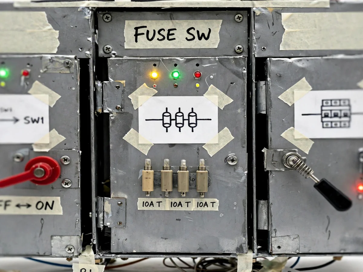
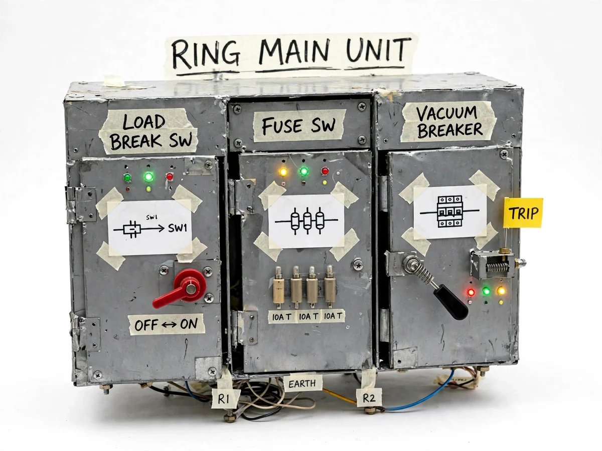
Distribution networks are built as rings so that no single cable fault has to black out a transformer: supply can reach any point from either direction around the ring. The ring main unit is the compact switchgear that makes this work at each transformer — typically two ring-feeder bays with load-break switches and one tee-off bay with a fused switch or circuit breaker protecting the transformer. Operating it correctly is a core distribution skill: isolate the faulted section, restore the healthy sections from the other side, earth before touching anything. This project builds a three-bay RMU as a bench model. Each bay is a fabricated compartment with a rotary operating handle driving a switch model; the tee-off bay carries cartridge fuses and a breaker model; a mimic single-line diagram with LEDs shows the ring, the switches and the fault point; mechanical interlocks enforce safe operating order; and a fault toggle lets the student run full isolation and back-feeding exercises. Every operation the student performs mirrors the real switching sequence.
How it works
- In the normal state both ring switches are closed, the tee-off breaker is closed, and the mimic shows the transformer fed with the ring continuous.
- The student operates the fault toggle, simulating a fault on the tee-off — the breaker model trips and its lamp changes on the mimic.
- The tee-off load-break switch is opened with its rotary handle, isolating the faulted transformer outlet; the mimic LEDs update.
- To restore the far side of the ring, the student opens the ring switch on the faulted side and confirms the remaining ring path on the mimic.
- The healthy side of the ring is verified continuous, demonstrating how the ring configuration keeps other transformers supplied.
- For the maintenance exercise, the isolated bay is earthed through the represented earth switch — only possible after isolation, as the interlock enforces — completing the safe isolation sequence.
- The student restores the unit to normal by reversing the sequence, and records each switching step for the report.
Tech stack:
- Ring main unit design
- Load-break switch theory
- Fuse-switch protection
- Switchgear interlocking
- Single-line diagrams
- Sheet-metal panel fabrication
- Low-voltage control wiring
- Distribution network operation
| Parameter | Value |
|---|---|
| Bays | 3 — two ring-feeder, one tee-off (design) |
| Ring bay switches | Rotary isolator models, 230 V / 10 A class (design) |
| Tee-off protection | Cartridge fuse models 10 A class + breaker model (design) |
| Mimic indication | Labeled single-line diagram with 12 V LEDs (design) |
| Cubicle | Fabricated sheet metal, approximately 600 × 400 × 300 mm (design) |
| Interlocks | Mechanical, enforcing isolation-before-earth sequence (design) |
| Operating handles | Rotary, one per bay (design) |
| Fault simulation | Toggle on tee-off bay (design) |
Project features
- [Three-bay cubicle] A fabricated sheet-metal cubicle with two ring-feeder bays and one tee-off bay, arranged as a real RMU lineup.
- [Load-break switch models] Rotary-handle isolators in each ring bay demonstrate making and breaking load current in the ring path.
- [Fused-switch / breaker bay] The tee-off bay carries cartridge fuse models and a breaker model protecting the transformer outlet, showing the protection function.
- [Mimic single-line diagram] A labeled SLD with LEDs tracks the ring, each switch position and the fault point, so switching operations read like a real panel.
- [Mechanical interlocks] Interlocks prevent unsafe sequences — for example, earthing a live bay — enforcing correct operating discipline.
- [Earthing switch representation] A represented earth switch shows the maintenance-earthing step that completes every isolation procedure.
- [Fault simulation toggle] A fault toggle on the tee-off lets the student run the full fault → isolate → back-feed exercise.
What is included
- Three-bay fabricated RMU cubicle with rotary handles
- Load-break switch models, fuse models and breaker model
- Mimic single-line panel with LED indication
- Mechanical interlocks and represented earth switch
- Wiring and schematic diagram of bays and mimic
- Project report PDF (background, RMU theory, switching procedures, exercises)
- PPT presentation for final review
- Viva Q&A preparation document (ring networks, load-break vs breaker, interlocks, earthing)
Limitations & prerequisites
- This is a low-voltage teaching model; real RMUs are 11/33 kV SF6 or vacuum switchgear with completely different insulation systems.
- No actual arc quenching is demonstrated — switching is a dry mechanical operation in the model.
- Operation is manual via rotary handles; many real RMUs are motorized or remote-operated.
- The earthing switch is representative, not a certified earthing device.
- Insulation clearances and fault ratings do not follow IEC switchgear standards — it is a classroom model.
Frequently Asked Questions
What is a ring main unit?
The compact switchgear installed where a distribution transformer connects to a ring network. It typically has two ring-feeder bays (so the ring passes through) and a tee-off bay that protects and isolates the transformer — switching, protection and metering in one cubicle.
Why build distribution as a ring?
Reliability. In a radial feeder a cable fault blacks out everything downstream; in a ring, supply reaches each point from either direction, so a faulted section can be isolated while the rest stays energized from the healthy side.
What is the difference between a load-break switch and a circuit breaker?
A load-break switch can make and break normal load current but not fault current; a circuit breaker interrupts fault current too. In the RMU the ring bays use load-break switches for switching, while the tee-off uses a fused switch or breaker for protection.
What does the fused switch in the tee-off protect?
The transformer. A fault in the transformer or its cables blows the fuses (or trips the breaker), isolating the fault before it can damage the ring or trip upstream protection.
How is a bay made safe for maintenance?
Isolate it from all sources (open both ring switches or the tee-off switch), then earth it — and only in that order. The model's interlock enforces exactly this sequence.
Is this project suitable for a final-year project?
Yes — for Electrical Engineering programs. It teaches ring-network operation, switchgear functions and safe switching discipline in a hands-on model. Suitable for B.E./B.Tech final-year projects in Electrical Engineering.
Components & software requirements
- Ring main unit design
- Load-break switch theory
- Fuse-switch protection
- Switchgear interlocking
- Single-line diagrams
- Sheet-metal panel fabrication
- Low-voltage control wiring
- Distribution network operation
Delivery information
Built-to-order project. Delivery timeline is shared after order confirmation based on current queue.
Support terms
Complete documentation, setup guide, and viva preparation included. Support for setup and explanation provided.