
More project photos (3)
The problem
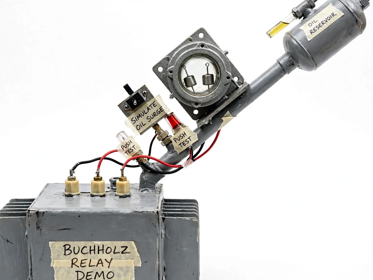
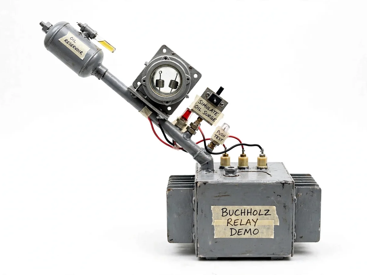
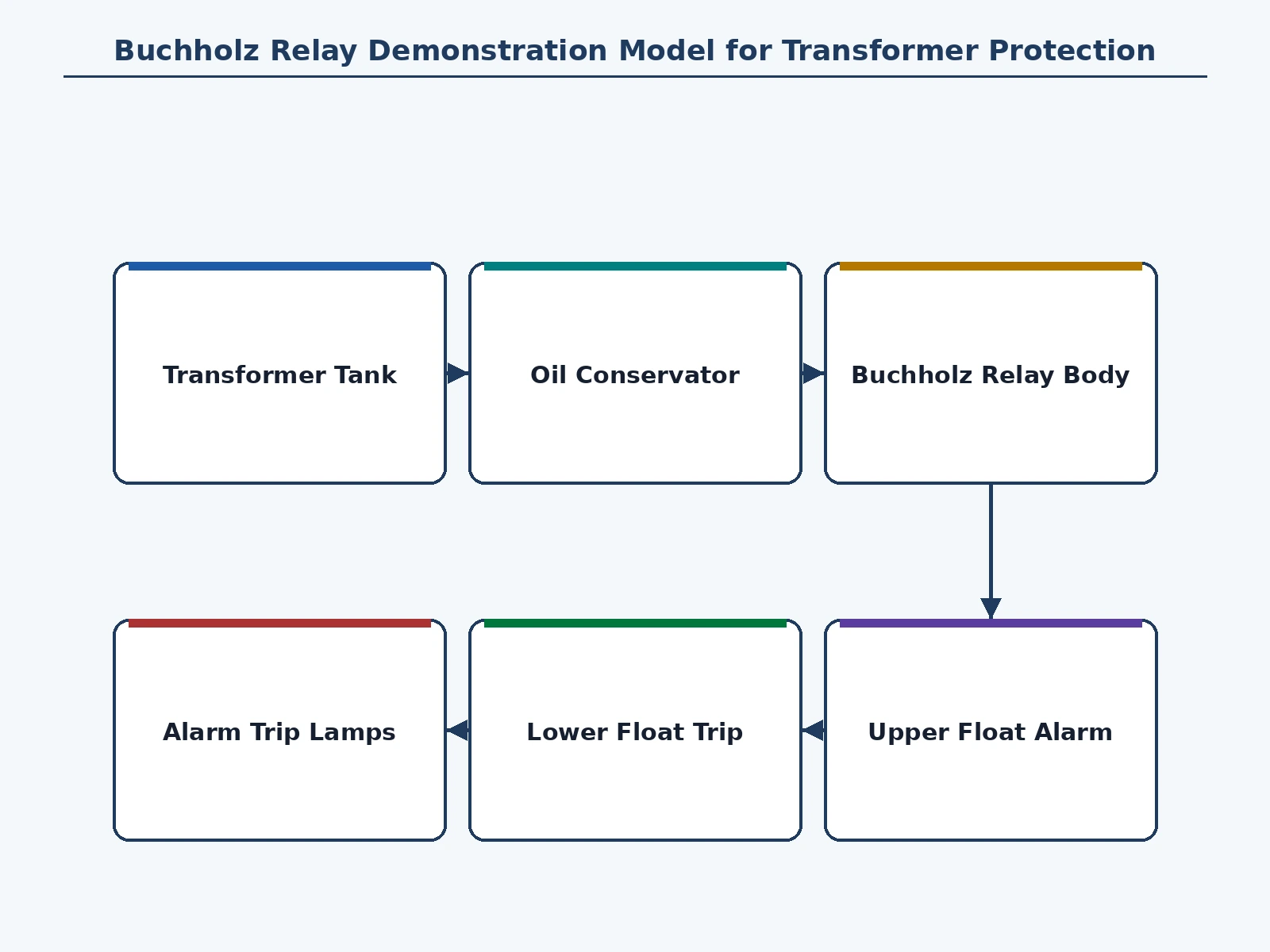
The Buchholz relay is one of the most examined devices in power-system protection, and one of the least understood by students — because it is usually taught as a diagram. In real substations it guards oil-immersed transformers: mounted in the inclined pipe between the main tank and the conservator, it watches for the two signatures of internal faults. Slow incipient faults like local overheating release gas that collects in the relay chamber and drops the oil level, tipping the upper float to raise an alarm; violent faults like winding short circuits drive an oil surge through the pipe that displaces the lower float and trips the breaker. This project makes both stages visible. A hand-fabricated model transformer tank with cooling fins and bushings connects through an inclined pipe to a cylindrical conservator, and the relay body carries a glass inspection window through which both floats are seen. A toggle mechanism simulates oil surge, push-to-test buttons exercise the alarm and trip lamp circuits, and everything is hand-labeled for demonstration.
Tests the lamps, pumps gas in for the alarm stage, and operates the surge toggle.
Follow the working sequence
How it works
- The tank and conservator are filled with the safe demo oil, and the relay chamber sits in the inclined pipe with the oil level visible through the glass window.
- The alarm and trip lamp circuits are tested with the push-to-test buttons, confirming both indication stages before the demo.
- To demonstrate the alarm stage, gas is introduced into the relay chamber (via the hand pump); bubbles collect at the top and the oil level in the chamber falls.
- The upper float drops with the oil level and its mercury-free micro-switch closes, lighting the amber alarm lamp — the incipient-fault signature.
- To demonstrate the trip stage, the surge toggle is operated, driving a visible oil surge through the pipe toward the conservator.
- The lower float is displaced by the surge and its switch closes, lighting the red trip lamp — the severe-fault signature — and the demo is reset by releasing the surge.
Tech stack:
- Buchholz relay protection principle
- Oil-immersed transformer protection
- Float-switch mechanisms
- Alarm and trip contact logic
- 12 V DC lamp indication circuits
- Sheet-metal model fabrication
- Low-voltage wiring and labeling
- Protection demonstration practice
| Parameter | Value |
|---|---|
| Tank model capacity | Approximately 8 L (design) |
| Conservator capacity | Approximately 2 L, cylindrical (design) |
| Relay pipe inclination | Approximately 5 degrees (design) |
| Floats | 2 — upper (alarm) and lower (trip) (design) |
| Alarm indication | Amber lamp, 12 V DC (design) |
| Trip indication | Red lamp, 12 V DC (design) |
| Test buttons | 2 — alarm test and trip test (design) |
| Demo oil | Non-toxic paraffin oil substitute, not transformer insulating oil (design) |
| Control supply | 12 V DC (design) |
Project features
- [Model transformer tank] A fabricated steel tank with cooling fins and three terminal bushings represents the transformer main tank, with a drain and fill arrangement for the demo oil.
- [Glass-windowed relay body] The relay chamber carries a round inspection window through which the two floats are directly visible, so float movement is seen, not assumed.
- [Two-stage float action] An upper float for the alarm stage and a lower float for the trip stage, each linked to its own lamp circuit, demonstrating gas-accumulation vs oil-surge behavior.
- [Simulated oil surge] A hand-operated surge mechanism displaces the lower float on demand, letting the student demonstrate the trip stage without any real fault.
- [Push-to-test buttons] Separate test buttons exercise the alarm and trip lamp circuits independently, for viva demonstrations of each stage.
- [Oil conservator] A cylindrical conservator vessel completes the oil circuit above the inclined pipe, showing the real mounting arrangement.
- [Labeled oil circuit] Handwritten labels trace the gas path, oil path and float positions, so the model explains itself during a demo.
What is included
- Fabricated model transformer tank with fins, bushings and oil fittings
- Buchholz relay body with glass window and two floats
- Cylindrical oil conservator with connecting inclined pipe
- Surge simulation mechanism and push-to-test button panel
- Alarm and trip lamp indication wiring
- Project report PDF (background, relay theory, two-stage action, demo procedure)
- PPT presentation for final review
- Viva Q&A preparation document (gas vs surge, float stages, mounting rules)
Limitations & prerequisites
- This is a demonstration model only — it never connects to a real energized transformer or its oil circuit.
- Gas accumulation and oil surge are simulated by hand, not produced by real electrical faults.
- It cannot demonstrate dissolved-gas analysis or real gas-sampling, which need laboratory equipment.
- Real Buchholz relays protect conservator-type transformers of larger ratings; the model is scaled down for the classroom.
- Float trip thresholds are demonstrative, not calibrated to real relay settings.
- The demo oil is a safe paraffin substitute — it does not replicate the insulating or cooling properties of transformer oil.
Frequently Asked Questions
What does a Buchholz relay detect?
Two things: gas released by slow incipient faults (overheating, partial discharge) which collects in the relay chamber, and the oil surge driven by violent internal faults (winding shorts). The first tips the upper float for alarm; the second displaces the lower float for trip.
Why does it have two floats?
Because the two fault signatures need different responses. Gas accumulation means a developing problem — alarm so the operator investigates. An oil surge means a severe fault — trip the breaker immediately. One relay, two stages, two contacts.
Why is the relay pipe inclined?
Gas bubbles from the tank must travel up the pipe to the conservator and get trapped in the relay chamber. The incline (a few degrees) guarantees the gas collects at the relay instead of bypassing it, and lets the chamber's oil level fall as gas accumulates.
Why isn't it used on small transformers?
Buchholz protection needs a conservator and an oil pipe to mount in, which small distribution transformers don't have. It is standard on larger oil-immersed units; small transformers rely on fuses and overcurrent protection instead.
Where exactly is it mounted?
In the pipe connecting the transformer main tank to the conservator, as close to the tank as practical, inclined toward the conservator. The demo model reproduces this exact arrangement.
Is this project suitable for a final-year project?
Yes — for Electrical Engineering programs. It turns the most diagram-taught protection device into a visible, operable two-stage demonstration. Suitable for B.E./B.Tech final-year projects in Electrical Engineering.
Components & software requirements
- Buchholz relay protection principle
- Oil-immersed transformer protection
- Float-switch mechanisms
- Alarm and trip contact logic
- 12 V DC lamp indication circuits
- Sheet-metal model fabrication
- Low-voltage wiring and labeling
- Protection demonstration practice
Delivery information
Built-to-order project. Delivery timeline is shared after order confirmation based on current queue.
Support terms
Complete documentation, setup guide, and viva preparation included. Support for setup and explanation provided.
Download free synopsis (PDF)
Enter your name and WhatsApp number — the synopsis PDF downloads immediately. We may send occasional project updates on WhatsApp; no spam.