
More project photos (3)
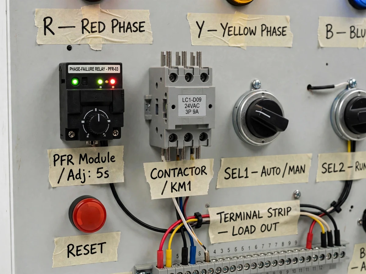
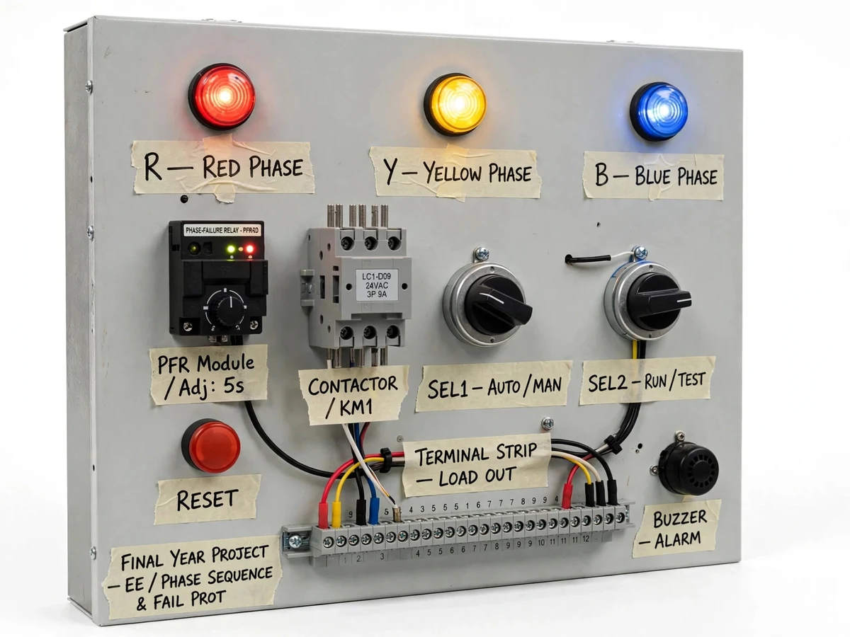
The problem
Three-phase supply faults are among the most common causes of motor damage in industry: a reversed phase sequence can spin a motor backward into mechanical damage, and a lost phase (single-phasing) overheats the remaining windings within minutes. Protection practice therefore relies on two ideas every electrical engineer must internalize — sequence detection and phase-failure monitoring — yet in college labs both are taught only as theory. This project closes that gap with a safe low-voltage demonstration panel: a 24 V 3-phase equivalent supply feeds a rotating-lamp phase-sequence indicator (R-Y-B vs R-B-Y), and a phase-failure relay supervises the same supply and trips a contactor when any phase is lost or badly unbalanced, cutting a small demo load while lighting an alarm lamp. Selector switches let the demonstrator deliberately swap two phases or drop one phase and watch the protection respond. Everything runs at extra-low voltage behind clearly labeled terminals, so the panel is safe to demonstrate live in a classroom or viva.
Low-voltage 3-phase trainer supply, isolated and fused for safe live demos.
Follow the working sequence
How it works
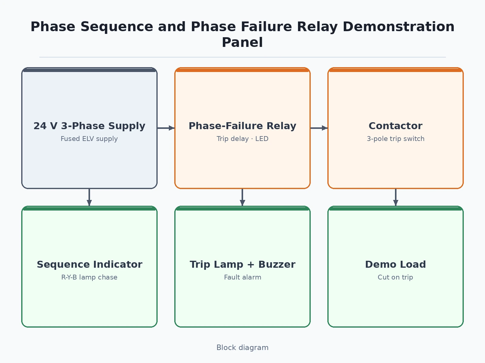
- A low-voltage 3-phase supply (approximately 24 V AC line-to-line equivalent, isolated and fused) feeds the panel input terminals.
- The phase-sequence indicator circuit connects three lamps so that with correct R-Y-B sequence they light in rotating order (clockwise chase); with any two phases swapped the rotation reverses (counter-clockwise).
- The phase-failure relay continuously supervises all three phases for loss, severe voltage unbalance and phase reversal, driving front-panel status LEDs.
- When the relay detects a fault it opens its output contact after its set trip delay (approximately 1–5 s), dropping the contactor coil.
- The contactor's main contacts open and disconnect the demo load (a small lamp/motor model), while an auxiliary contact lights the trip lamp and sounds the buzzer.
- Using the selector switches the demonstrator can introduce a swapped sequence or a dropped phase; pressing the reset push button restores normal operation once the selector is returned to healthy.
Tech stack:
- 24 V AC 3-phase equivalent supply (isolated, fused)
- Phase sequence indicator module (rotating-lamp type)
- Phase-failure / single-phasing relay with trip delay
- 3-pole contactor with auxiliary contacts
- Panel-mount selector switches and push buttons
- Indicating lamps (red/yellow/blue + trip lamp), buzzer
- DIN rail, terminal strips, panel enclosure
| Parameter | Value |
|---|---|
| Supply | 24 V AC 3-phase equivalent, isolated (design target) |
| Sequence indication | Lamp rotation; CW = R-Y-B, CCW = R-B-Y |
| Relay supervision | Phase loss, unbalance, reversal (module dependent) |
| Trip delay | Approximately 1–5 s, adjustable (design target) |
| Contactor | 3-pole, coil matched to trainer supply (approximate) |
| Demo load | Low-voltage lamp / small motor model (approximate) |
| Panel size | Approximately 450 × 350 × 120 mm (design target) |
| Safety | ELV throughout; fused supply; labeled terminals |
| Alarm | Trip lamp + buzzer, manual reset |
Project features
- [Rotating-lamp sequence indicator] Three phase lamps wired in sequence-detection order that visually chase clockwise for R-Y-B and counter-clockwise for R-B-Y, making correct vs reversed sequence instantly readable.
- [Phase-failure / single-phasing relay] A dedicated supervision relay that detects phase loss, severe unbalance and (on supported modules) phase reversal, with adjustable trip delay and LED status indication.
- [Contactor trip demonstration] The relay's output contact drops a 3-pole contactor that switches the demo load, so tripping is a real power-circuit interruption — not a simulation on a microcontroller pin.
- [Deliberate-fault selector switches] Panel-mounted selectors let the demonstrator swap two phases or drop any single phase at will, so sequence reversal and single-phasing can be reproduced repeatably for an audience.
- [Low-voltage safe trainer] Runs on an extra-low-voltage 3-phase equivalent (approximately 24 V AC) with a fused, isolated supply and clearly labeled terminals — safe to operate live in a lab or viva hall.
- [Alarm and status indication] Separate trip/alarm lamp plus buzzer annunciate the fault, with a reset push button that restores the contactor once the fault is cleared.
- [Hand-wired panel construction] DIN-rail mounted components with marked terminal strips and a wiring diagram in the documentation, so the build itself demonstrates standard panel-wiring practice.
What is included
- Assembled and wired demonstration panel (relay, contactor, lamps, selectors)
- Isolated low-voltage 3-phase trainer supply
- Wiring diagram and terminal chart
- Project report PDF (theory: sequence, protection, build, demonstration procedure)
- PPT presentation for final review
- Viva Q&A preparation document (sequence vs reversal, single-phasing effects, relay settings)
- Operating and fault-injection procedure sheet
Limitations & prerequisites
- Extra-low-voltage trainer only — it does not connect to 230/415 V mains and cannot demonstrate real mains-level protection behavior; sequence detection is shown at approximately 24 V AC.
- The demo uses a lamp/motor model as load, not a real 3-phase induction motor; effects like actual motor heating during single-phasing are explained in the report, not reproduced.
- Relay trip characteristics are those of the supplied protection module — timing and unbalance thresholds are approximate module ratings, not calibrated measurements.
- The exact unbalance level that triggers a trip depends on the module; very small voltage dips may not trip it — this is a module limit, stated in the documentation.
- The panel demonstrates protection logic; it is not a certified protection device and must never be wired into a real installation.
Frequently Asked Questions
How does the lamp rotation show phase sequence?
The three lamps are wired so that with R-Y-B sequence they chase in clockwise order; swapping any two phases reverses the rotation to counter-clockwise. It is the classic electrical-trade sequence test rendered as a visible demo.
What faults does the relay demonstrate?
Phase loss (single-phasing), severe voltage unbalance, and phase reversal on modules that support it — each drops the contactor and raises the trip alarm after the set delay.
Is it safe to demonstrate live?
Yes — the entire panel runs at extra-low voltage (approximately 24 V AC) from an isolated, fused supply with labeled terminals. It never connects to mains.
Can it run a real 3-phase motor?
No — the load side is a low-voltage lamp/motor model. The panel demonstrates detection and tripping logic; motor behavior under faults is covered in the report's theory section.
What is single-phasing and why does it matter?
Losing one phase of a 3-phase supply forces the remaining two to carry the load, overheating motor windings — one of the most common causes of industrial motor burnout, which is exactly why phase-failure relays are standard protection.
Is this project suitable for a final-year project?
Yes — for Electrical Engineering programs. It covers 3-phase fundamentals, sequence, unbalance, protection relaying and panel wiring, with a live, repeatable demonstration. Suitable for B.E./B.Tech final-year projects in Electrical Engineering.
Components & software requirements
- 24 V AC 3-phase equivalent supply (isolated, fused)
- Phase sequence indicator module (rotating-lamp type)
- Phase-failure / single-phasing relay with trip delay
- 3-pole contactor with auxiliary contacts
- Panel-mount selector switches and push buttons
- Indicating lamps (red/yellow/blue + trip lamp), buzzer
- DIN rail, terminal strips, panel enclosure
Delivery information
Built-to-order project. Delivery timeline is shared after order confirmation based on current queue.
Support terms
Complete documentation, setup guide, and viva preparation included. Support for setup and explanation provided.
Download free synopsis (PDF)
Enter your name and WhatsApp number — the synopsis PDF downloads immediately. We may send occasional project updates on WhatsApp; no spam.