
More project photos (2)

The problem
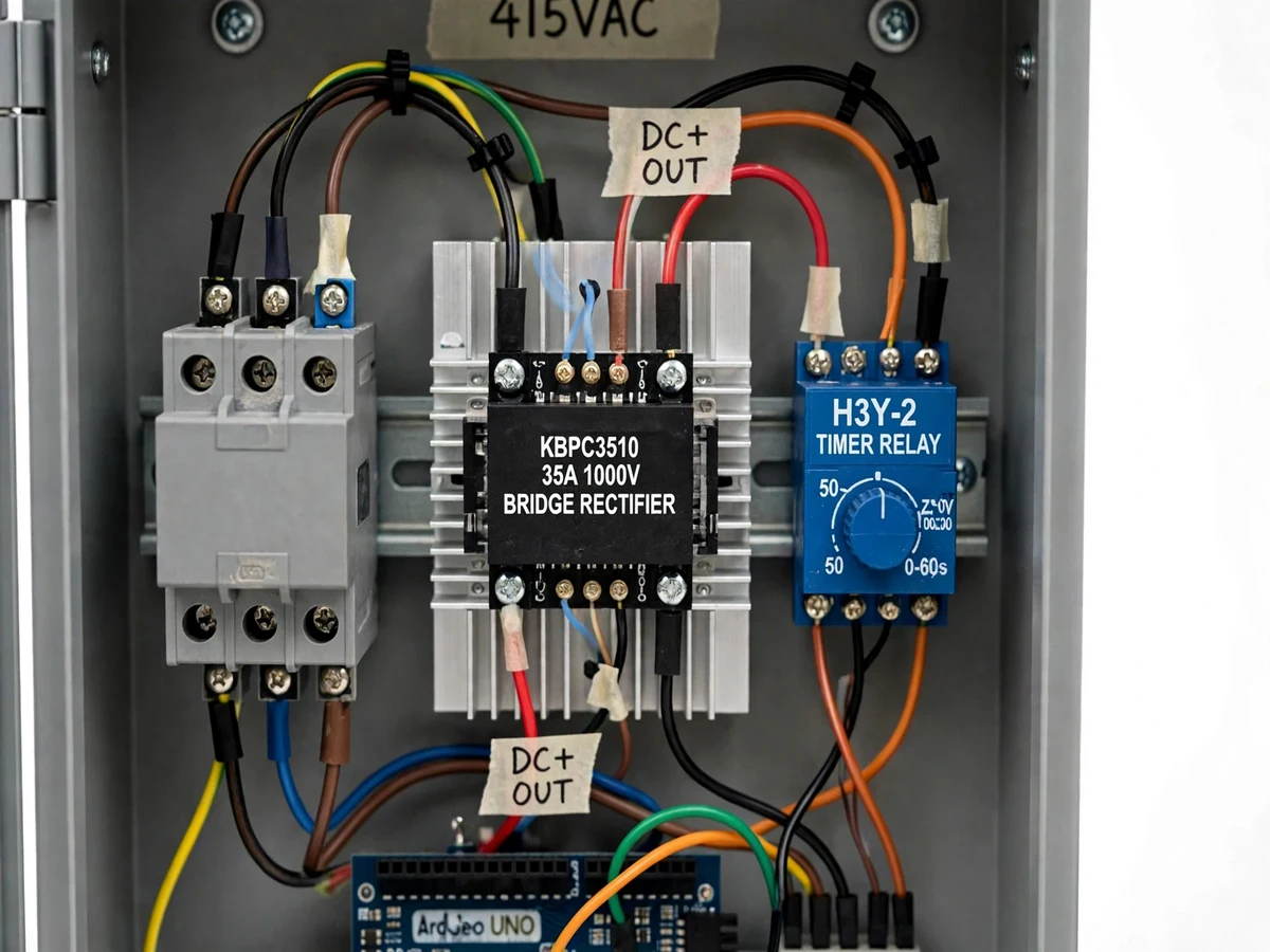
Every electric drive needs a way to stop: coasting is free but slow, mechanical brakes wear, and plugging (reverse-current braking) stresses the motor with huge currents. DC injection braking sits in the sweet spot — inject DC into the stator after cutting the AC, and the stationary field produces a braking torque that stops the rotor quickly with no mechanical contact and modest current. It is standard practice on machine tools, cranes and conveyors, yet most students only read the theory. This project makes it demonstrable: a panel with a main contactor, a braking contactor, a bridge-rectifier DC source on a heatsink, a timer relay for braking duration, Arduino sequence supervision and a digital RPM meter on the door, wired to a 0.5 HP three-phase demo motor. The student measures and compares coast-down time versus braked stop time — real data for the report.
How it works
- The student wires the panel per the schematic: incomer, main (AC) contactor, braking (DC) contactor, rectifier+fuse DC source, timer relay, Arduino supervisor, RPM meter and push-buttons.
- Pressing start runs the demo motor on 415 V AC through the main contactor; the RPM meter shows running speed (approximately 1440 rpm for the demo motor).
- Pressing stop drops the main contactor (AC disconnected) and, through the interlocked sequence, closes the braking contactor to inject DC into two stator phases.
- The stationary DC field brakes the rotor; the timer relay holds the injection for the set duration while the RPM display shows the rapid speed decay.
- When the timer elapses, the braking contactor opens, the sequence resets, and the panel is ready for the next run — or the next start.
- The student runs the test procedure: times the coast-down stop, then times braked stops at several timer settings, and tabulates the comparison for the report.
Tech stack:
- 3-phase main contactor + braking contactor with interlocking
- KBPC3510-class bridge rectifier on aluminum heatsink
- H3Y-2-class timer relay (0–60 s range)
- Arduino Uno sequence supervisor (C/C++ firmware)
- Digital panel RPM meter
- 0.5 HP three-phase induction demo motor
- Start/stop/e-stop push-buttons, status lamps
- Fused DC injection circuit, DIN-rail panel wiring
| Parameter | Value |
|---|---|
| Supply | 415 V AC, 3-phase, 50 Hz (design) |
| Demo motor | 0.5 HP, 3-phase, approximately 1440 rpm (design) |
| DC source | Bridge rectifier, fused at approximately 2 A (design) |
| Braking timer | Adjustable approximately 1–60 s (design) |
| Expected braked stop | Approximately 3–8 s from full speed (expected, load dependent) |
| Expected coast-down | Approximately 30–60 s from full speed (expected, load dependent) |
| Panel | Wall-mount metal enclosure with door-mounted controls (design) |
Project features
- [Contactor-based AC/DC changeover] A main contactor and a braking contactor with electrical interlocking swap the stator between the 415 V AC supply and the DC injection source — the two can never connect simultaneously.
- [Rectifier DC source on heatsink] A bridge rectifier module on an aluminum heatsink provides the injection current from the AC supply; a fuse protects the DC circuit.
- [Timer-controlled braking duration] An H3Y-2-class timer relay sets how long DC is applied, so the student can study the effect of braking time on stop performance.
- [Arduino sequence supervision] The Arduino enforces the correct order (run → stop command → AC off → DC on → timer → DC off), drives status indication, and blocks illegal sequences.
- [Digital RPM display] A panel RPM meter shows live motor speed, so the audience watches the speed collapse during braking — the demo's centerpiece.
- [Stop-time measurement procedure] A documented procedure measures coast-down time vs DC-braked stop time at several timer settings, giving the report genuine comparative data.
- [Emergency stop and interlocks] A latching e-stop drops all contactors, and the interlock logic prevents DC injection while the motor is still on AC.
What is included
- Wired DC injection braking panel (contactors, rectifier, timer, supervisor, RPM meter)
- 0.5 HP three-phase induction demo motor wired to the panel
- Control schematic, wiring diagram and bill of materials
- Stop-time measurement and comparison test procedure
- Project report PDF (braking theory, panel design, measured stop-time comparison procedure)
- PPT presentation for final review
- Viva Q&A preparation document (DC braking physics, contactor interlocking, timer control)
Limitations & prerequisites
- A demonstration panel with a fractional-HP demo motor — it teaches the braking method, not industrial drive commissioning.
- The demo runs on a real 415 V three-phase supply, which the student's institution must provide with proper earthing.
- 415 V work is inherently hazardous: the manual mandates qualified supervision, with shrouded terminals and an interlocked panel door.
- DC injection heats the rotor: repeated braking runs need cool-down gaps per the test procedure; it is not a continuous-duty brake.
- Braking torque falls to zero at standstill, so DC injection cannot hold a load against gravity — a mechanical brake is still needed for hoists (stated honestly in the report).
- Stop times are expected ranges; the student's measured values are the report's data.
Frequently Asked Questions
How does injecting DC actually brake the motor?
DC in the stator makes a stationary (non-rotating) magnetic field. The spinning rotor cuts it, inducing rotor currents whose interaction with the field produces torque opposing the rotation — braking without any mechanical contact.
Why not just use a mechanical brake?
Mechanical brakes wear and need maintenance; DC injection has no wearing parts and gives smooth, adjustable stops. Industry uses it on machine tools and conveyors where fast, clean stops matter.
What is the difference from plugging?
Plugging reverses two supply phases so the motor torques backward — effective but with very high currents and a risk of the motor reversing. DC injection is gentler and cannot reverse the motor.
Why does the panel need two contactors with interlocking?
One connects AC for running, the other connects DC for braking. If both closed together, the DC source would short the AC supply — the interlocking makes that impossible by both wiring and logic.
How is the stop time actually measured?
With the RPM meter and a stopwatch per the test procedure: time from stop command to zero RPM, first coasting, then with DC injection at several timer settings, and compare.
Is this project suitable for a final-year project?
Yes — for Electrical programs. It demonstrates electric braking methods, contactor control, protection interlocking and experimental measurement. Suitable for B.E./B.Tech final-year projects in Electrical.
Components & software requirements
- 3-phase main contactor + braking contactor with interlocking
- KBPC3510-class bridge rectifier on aluminum heatsink
- H3Y-2-class timer relay (0–60 s range)
- Arduino Uno sequence supervisor (C/C++ firmware)
- Digital panel RPM meter
- 0.5 HP three-phase induction demo motor
- Start/stop/e-stop push-buttons, status lamps
- Fused DC injection circuit, DIN-rail panel wiring
Delivery information
Built-to-order project. Delivery timeline is shared after order confirmation based on current queue.
Support terms
Complete documentation, setup guide, and viva preparation included. Support for setup and explanation provided.