
More project photos (4)
The problem
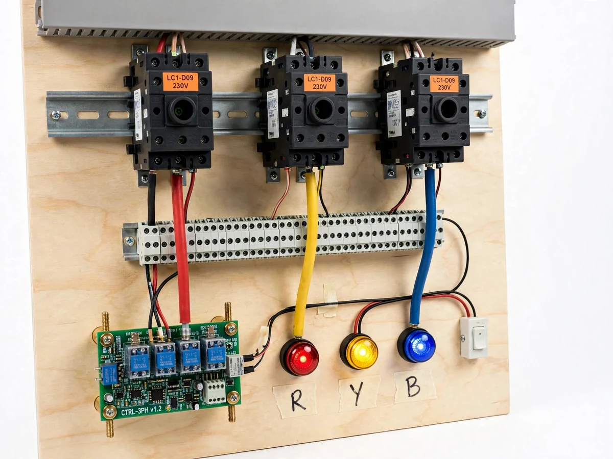
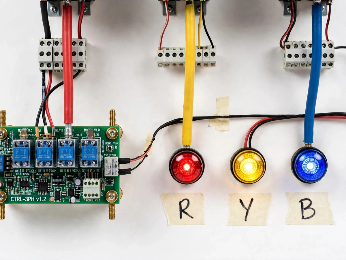
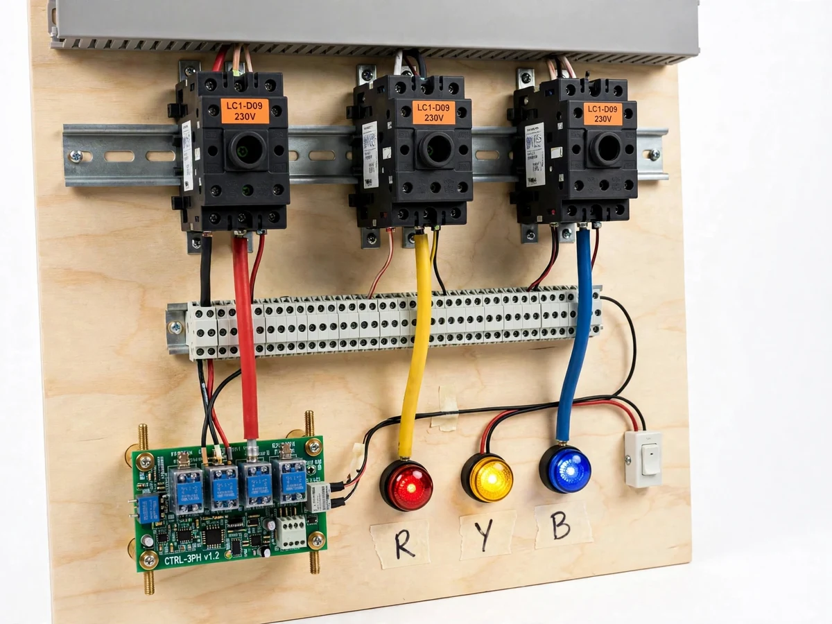
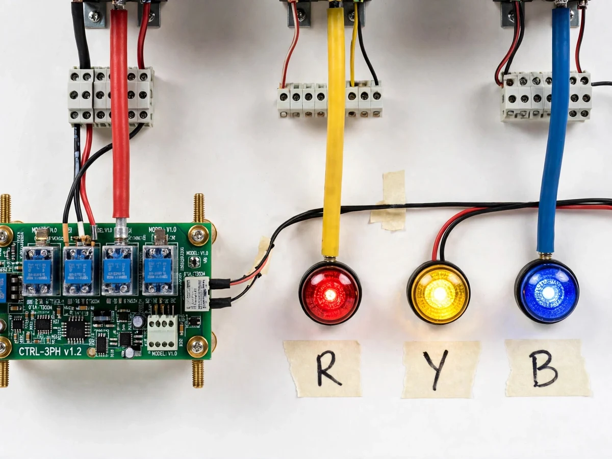
An automatic phase selector for single-phase loads is a panel that takes a three-phase 400 V input and delivers one healthy 230 V single-phase supply to a load. It exists because single-phase loads wired to one phase of a three-phase supply stop dead when that phase fails or sags — homes, workshops and small offices routinely lose lighting, refrigeration or pump power to exactly this failure. The selector fixes it automatically: isolated sensing circuits watch the R, Y and B phases, pick the first healthy phase in fixed priority, and energize a contactor connecting that phase to the load. If the active phase drops below the undervoltage threshold of about 180 V (adjustable), the panel switches to the next healthy phase after a break-before-make dead time of roughly 100–200 ms, so two phases are never paralleled. It is neither a single-phase preventer (which protects three-phase motors by tripping) nor a mains–generator changeover (which swaps two independent sources).
Three-phase 400 V line-to-line input feeding the selector panel.
Follow the working sequence
How it works
From sensing to switching, the mechanism runs in a fixed loop. First, three isolated sensing circuits — step-down transformers with rectification and a comparator stage — report whether the R, Y and B phases are present and above the undervoltage threshold of about 180 V. Next, the selection stage (relay logic or a small microcontroller) picks the highest-priority healthy phase in the fixed order R, then Y, then B. Finally, the switching stage energizes the matching power contactor, and a hardware interlock — the normally-closed auxiliary contact of each contactor wired in series with the other two coils — makes it physically impossible for two contactors to pull in together. Changeover is break-before-make: the outgoing coil de-energizes first, and an off-delay of roughly 100–200 ms (design target) guarantees its contacts have opened before the next closes, so no two phases are ever paralleled across the 400 V line-to-line gap. LEDs show which phase is live and which are faulted.
- Each of the three phases feeds an isolated step-down sensing transformer; the secondary is rectified and divided down to a safe signal voltage of approximately 5 V DC at nominal input (expected).
- Comparator stages compare each signal against the undervoltage reference set by a trimmer (approximately 180 V line-neutral threshold, adjustable); an optocoupler carries each phase's healthy/fault flag to the logic stage.
- The selection logic scans the flags in the fixed order R, then Y, then B, and chooses the first healthy phase — no operator action needed.
- The logic energizes the matching power contactor, which connects that phase (plus neutral) to the load terminals; the LEDs update to show the active and faulted phases.
- The hardware interlock chain — the NC auxiliary of each contactor in series with the other coils — continuously prevents a second contactor from pulling in, regardless of what the logic outputs.
- If the active phase's flag drops, the logic de-energizes its contactor and waits the break-before-make dead time of approximately 100–200 ms (design target) before energizing the next healthy phase.
- If no phase is healthy, all contactors stay open and the fault LEDs show the condition until a phase recovers.
Tech stack:
- 230 V AC / 400 V AC three-phase wiring hardware
- Step-down transformers + bridge rectifiers (sensing)
- LM393-type comparators with trimmer references
- PC817-type optocouplers (signal isolation)
- Power contactors with NC auxiliary interlock chain
- ATmega328-class microcontroller or relay logic (selection control)
- DIN rail, terminal blocks, panel enclosure
- Multimeter + clamp meter (testing and setpoint calibration)
| Parameter | Value |
|---|---|
| Input supply | Three-phase, 400 V line-to-line nominal (India standard) |
| Output | Single-phase, 230 V line-to-neutral nominal (design target) |
| Per-phase sensing | Approximately 0–300 V AC via isolated step-down transformer |
| Undervoltage threshold | Approximately 180 V line-neutral, trimmer-adjustable (design target) |
| Phase priority | Fixed R > Y > B (configurable in firmware) |
| Switching devices | 3 × power contactors, approximately 9 A AC-3 rating (design target) |
| Interlock | Hardware NC-auxiliary chain + off-delay break-before-make (configurable) |
| Changeover dead time | Approximately 100–200 ms (design target) |
| Phase indication | Panel LEDs for R/Y/B live and fault |
| Maximum load | Approximately 1–2 kW single-phase (design target, contactor-dependent) |
| Panel size | Approximately 300 × 250 × 150 mm (expected) |
| Control supply | 230 V AC derived via control transformer (design target) |
Project features
Four capabilities define this build. First, per-phase health sensing: three isolated step-down sensing circuits report presence and undervoltage on each phase, with a comparator stage that flags any phase below about 180 V (adjustable). Second, fixed-priority selection: the control logic always picks the highest-priority healthy phase in R, then Y, then B order, and automatically re-evaluates the moment the active phase degrades. Third, contactor switching with hardware interlocking: three power contactors route the chosen phase to the load, and the normally-closed auxiliary contact of each contactor is wired in series with the other two coils, so two contactors physically cannot pull in together — even a welded main contact holds its own auxiliary open and blocks the rest. Fourth, safe changeover timing: break-before-make sequencing with roughly 100–200 ms of dead time guarantees the outgoing contactor's contacts have opened before the next closes, eliminating any chance of a 400 V phase-to-phase short.
- [Per-phase presence + undervoltage sensing] Three transformer-isolated sensing circuits monitor R, Y and B independently; a comparator with hysteresis flags a phase as unhealthy below approximately 180 V line-neutral, adjustable via an onboard trimmer.
- [Fixed-priority selection logic] The controller selects the highest-priority healthy phase (R > Y > B) and re-runs the selection the instant the active phase fails, with no manual intervention.
- [Hardware-interlocked contactor switching] Three power contactors route the chosen phase to the load; each contactor's NC auxiliary contact is wired in series with the competing coils so simultaneous closure is mechanically impossible.
- [Break-before-make dead time] An off-delay of approximately 100–200 ms between de-energizing the outgoing contactor and energizing the next guarantees contact separation before the new phase connects.
- [LED phase-status indication] Panel-mounted red, yellow and blue LEDs show which phase is feeding the load, with a separate fault indication for each unhealthy phase.
- [Welded-contact interlock reasoning] The interlock is wired in hardware precisely because firmware alone cannot stop a welded contactor: a stuck armature holds its own NC auxiliary open, which keeps the competing coils de-energized regardless of what the code commands.
- [Single-phase 230 V output] The selected phase is delivered with the neutral to a standard 230 V output for lamps, pumps, chargers and similar single-phase loads.
What is included
- Working three-phase selector panel prototype (wired and bench-tested)
- Control logic firmware/source or relay ladder documentation
- Complete circuit and wiring diagrams
- Component list with ratings
- Undervoltage setpoint calibration procedure
- Project report PDF (background, design calculations, methodology, results)
- PPT presentation for final review
- Viva Q&A preparation document
Limitations & prerequisites
- Three-phase 400 V wiring is a genuine shock and arc hazard: installation and the demo must be supervised by a qualified electrician; the panel is a lab prototype, not an industrial-certified system.
- Changeover is not seamless — the load sees a brief interruption of approximately 100–200 ms (design target) at every switchover, so equipment that cannot tolerate a momentary outage needs its own backup.
- If all three phases fail, the selector has nothing to select: it opens all contactors and waits, with no UPS or battery function.
- The undervoltage threshold is a fixed setpoint per installation; a brief sag below it triggers a switchover even if the phase recovers immediately.
- Selection follows fixed priority (R > Y > B) rather than balancing load across phases.
- Maximum load is bounded by the contactor rating (approximately 1–2 kW single-phase in this build); larger loads need re-sized contactors.
- The prototype enclosure and neutral/earth wiring are sized for bench demonstration, not for unattended commercial deployment.
Frequently Asked Questions
Is this project suitable for a final-year project?
Yes — it fits Electrical and E&TC final-year programs directly. It demonstrates three-phase supply fundamentals, sensing and comparator design, contactor control, electrical interlocking practice and safety-aware panel wiring, all of which appear in power-systems and switchgear coursework. The build is compact enough for a bench demo yet rich enough for a confident viva: the student can explain every stage from sensing to switching. Report, PPT and viva Q&A are included.
How is this different from a single-phase preventer?
A single-phase preventer monitors a three-phase supply feeding a three-phase motor and trips the motor when any phase is lost, because running a motor on two phases burns its windings. The phase selector solves the opposite problem: it keeps a single-phase load alive by moving it to a healthy phase.
The preventer protects motors by disconnecting power; the selector keeps loads powered by re-routing it. They share only the sensing idea — their purpose, output action and target load are all different.
How is this different from an automatic mains–generator changeover?
A mains–generator changeover (ATS) switches a load between two independent sources — the grid and a standby generator. The phase selector works within one three-phase supply, choosing the healthiest of its three phases. The changeover answers "which source should feed the load?"; the selector answers "which phase of this supply should feed the load?". The selector needs no second source and no generator, just the existing three-phase connection.
What happens when two or three phases are healthy at the same time?
The selector always connects the highest-priority healthy phase — R first, then Y, then B — so the load sees one deterministic supply. If R is healthy, R feeds the load even when Y and B are also fine; only when R degrades below the undervoltage threshold does the panel step down the priority list. This fixed order keeps the logic simple, predictable and easy to explain in a viva.
Why must the interlock be wired in hardware instead of just coded in software?
Because a welded contactor defeats code. If the outgoing contactor's main contacts weld shut, firmware commanding "coil off" changes nothing — that phase stays connected to the load while the controller believes it is safe. No software sequence can open a physically welded contact.
With the normally-closed auxiliary contact of each contactor wired in series with the other two coils, a welded contactor holds its own auxiliary open and the competing contactors physically cannot pull in, no matter what the software commands. The interlock is the one protection that survives the exact failure mode contactors are known for.
What load can it power, and what supply does it need?
The bench build drives approximately 1–2 kW of single-phase 230 V load — lamps, pumps, chargers and small machines — and the contactor rating sets the ceiling, so larger contactors can be specified for heavier loads. For the demonstration it needs a three-phase 400 V supply (or a three-phase variac/simulator in the lab); the sensing and control electronics draw only a few watts from a control transformer.
Components & software requirements
- 230 V AC / 400 V AC three-phase wiring hardware
- Step-down transformers + bridge rectifiers (sensing)
- LM393-type comparators with trimmer references
- PC817-type optocouplers (signal isolation)
- Power contactors with NC auxiliary interlock chain
- ATmega328-class microcontroller or relay logic (selection control)
- DIN rail, terminal blocks, panel enclosure
- Multimeter + clamp meter (testing and setpoint calibration)
Delivery information
Built-to-order project. Delivery timeline is shared after order confirmation based on current queue.
Support terms
Complete documentation, setup guide, and viva preparation included. Support for setup and explanation provided.
Download free synopsis (PDF)
Enter your name and WhatsApp number — the synopsis PDF downloads immediately. We may send occasional project updates on WhatsApp; no spam.