
More project photos (2)
The problem
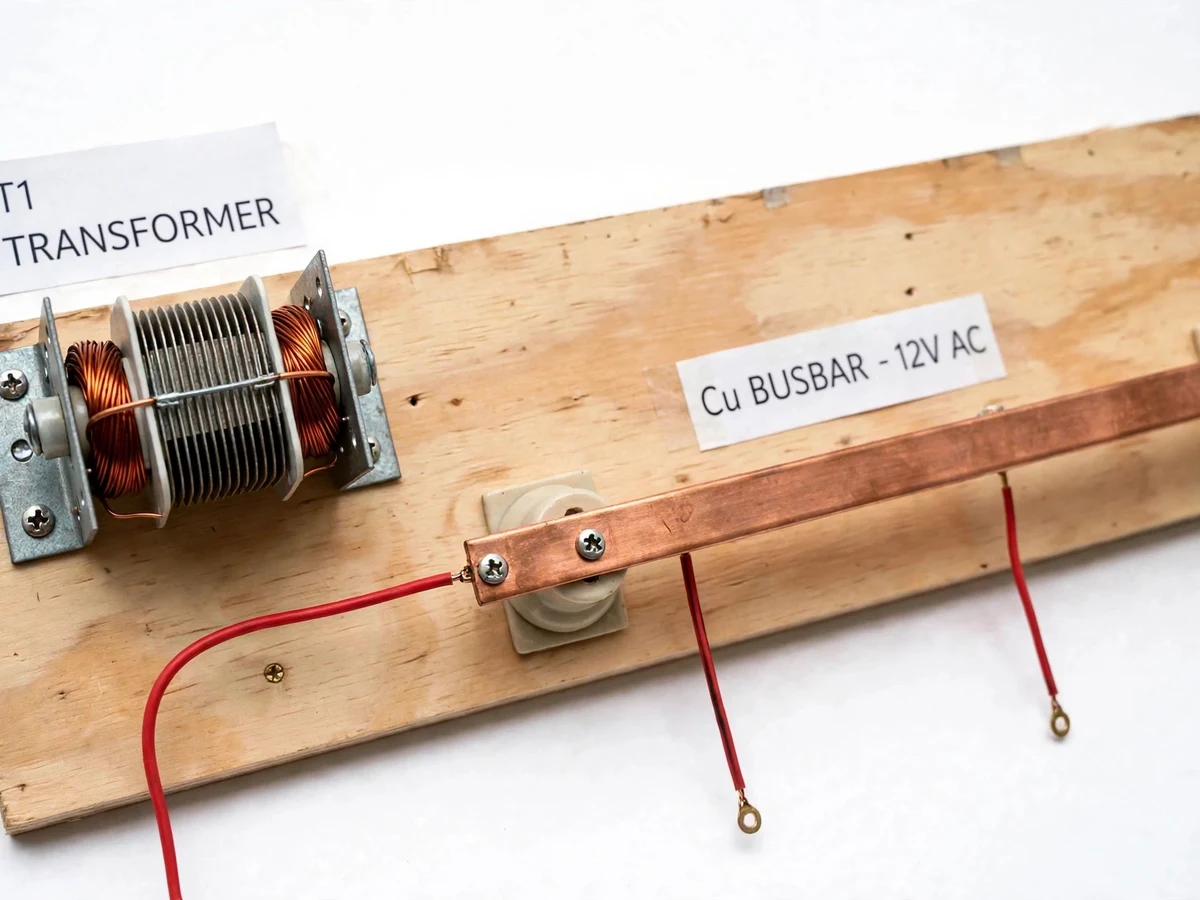
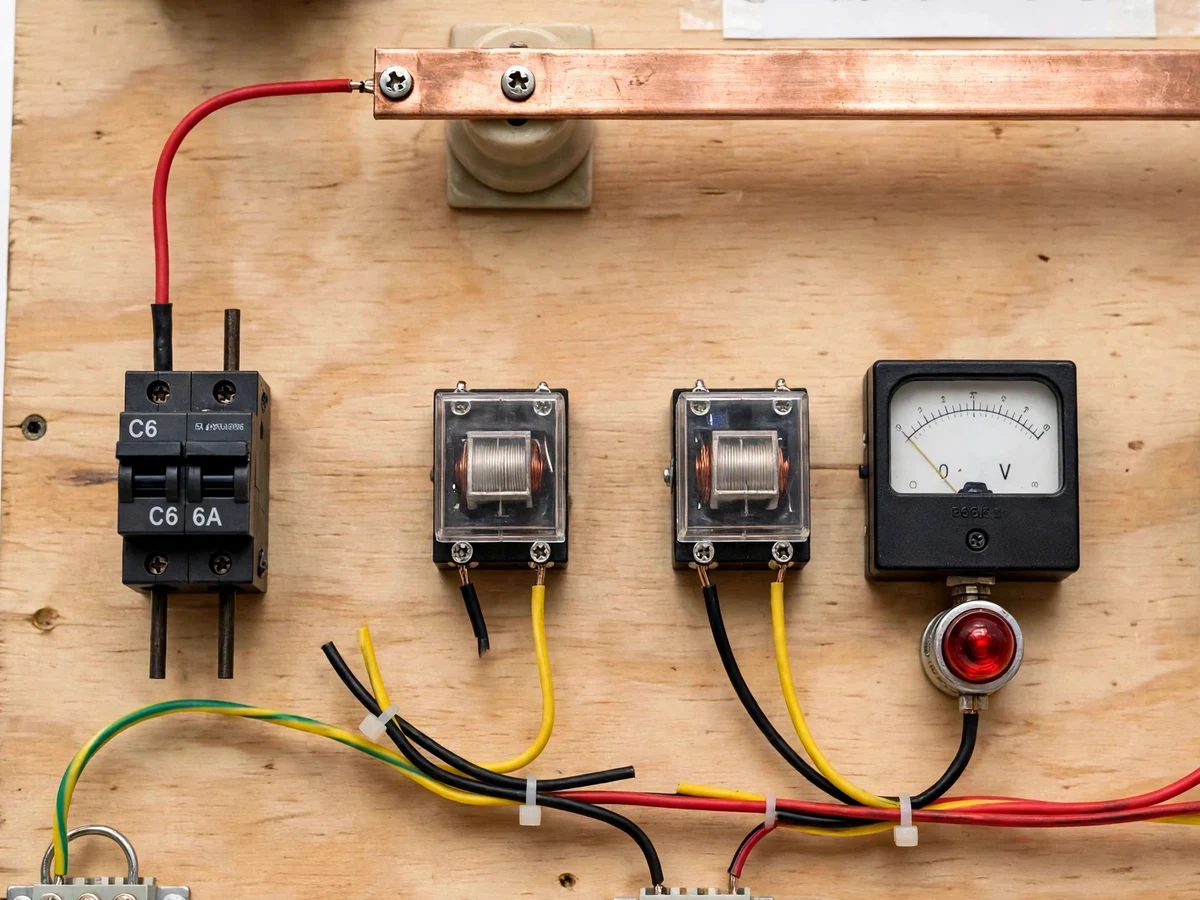
The Mini Substation Model with Transformer Protection Relays and Busbar for Lab Demonstration is a bench-scale electrical substation layout built for laboratory teaching. It reproduces the core chain of a substation at safe demonstration voltages: an incoming supply feeds a small single-phase transformer, the transformer output connects to a copper busbar, and the busbar distributes power to separate outgoing feeders through switches, meters, and protection relays. Each feeder can be isolated independently, and a simulated fault on any feeder trips only that feeder's relay, leaving the other feeders energised. Students trace voltage from source to load with a multimeter, read current on panel meters, and observe how busbar arrangement, transformer tapping, and relay coordination work together. The model is built on a labelled plywood base with colour-coded wiring, miniature circuit breakers, and indicator lamps, so the whole layout stays visible during a demonstration.
Electrical students often study substations only as single-line diagrams, which hides the physical questions that matter in a laboratory: where the busbar sits, how a feeder is isolated, and what actually opens when a relay operates. This model answers those questions on the bench. It is a scaled demonstration model with low-voltage safe demonstration circuits, not a real grid substation, and it never handles real distribution voltages or currents. Every part is labelled, every feeder is separately metered, and every trip is visible as a lamp going out and a relay changing state.
230 V AC mains feed the enclosed step-down stage.
Follow the working sequence
How it works
Power in the Mini Substation Model travels one visible chain from source to load. The incoming supply first passes through a master switch and a meter, then feeds the primary of a small single-phase demonstration transformer. The transformer secondary connects to a copper busbar, which acts as a common distribution node for three outgoing feeders. Each feeder leaves the busbar through its own switch, meter, miniature circuit breaker, and protection relay before reaching its load lamps. Under normal load, all three feeders stay energised and the meters show modest currents. When a fault is simulated on one feeder, that feeder's relay senses the overcurrent, its contacts open, and its breaker and lamp drop out, while the busbar and the healthy feeders keep running. A protection relay trips not because it senses danger in the abstract, but because a measured current crossing a set threshold energises a coil that opens a contact: measurement, decision, action, in that order.
- The master switch is closed and the incoming supply is metered, confirming the model is energised before any feeder is switched in.
- The demonstration transformer steps the supply down to the busbar demonstration voltage, and the tap selector is set to the position stated in the demonstration script.
- The busbar voltmeter is read to confirm the common distribution voltage, and the busbar is checked as the single node feeding all three feeders.
- Each feeder is switched in one at a time, and its ammeter and indicator lamp confirm that the feeder is carrying load.
- A fault is simulated on one feeder with its fault-simulation button, driving that feeder's current past its relay threshold through a current-limiting arrangement.
- The faulty feeder's relay trips, its contacts open, and its lamp goes out, while the busbar voltmeter and the healthy feeders' meters show that supply continues.
- The fault button is released, the tripped feeder is reset, and the feeder is switched back in, restoring normal three-feeder operation.
Comparison with alternatives
| Approach | What students see | Protection behaviour | Best use |
|---|---|---|---|
| This lab substation model | Complete chain: supply, transformer, busbar, feeders, relays | A simulated fault trips only the faulty feeder | Teaching substation layout and protection coordination |
| Wiring-practice trainer panel | Individual wiring circuits and switch boards | No coordinated feeder protection | Practising wiring and circuit assembly skills |
| Software-only power-system simulation | Calculated voltages, currents, and fault curves | Simulated trips with no physical contacts or lamps | Studying fault calculations and load-flow theory |
| Single-transformer demo | One transformer stepping voltage up or down | No busbar, no feeders, no selective tripping | Introducing transformer ratios in isolation |
Tech stack:
- Single-phase demonstration transformer
- Copper busbar with 3 feeder circuits
- Electromagnetic protection relays
- Miniature circuit breakers
- Panel voltmeter and ammeters
- Fault-simulation push buttons
- Indicator lamps and selector switches
- Colour-coded wiring and terminal blocks
| Parameter | Value |
|---|---|
| Demonstration transformer | Single-phase, 230 V AC primary to 12 V AC secondary (design target) |
| Transformer secondary rating | 3 A (design target) |
| Busbar | Copper strip busbar at 12 V AC demonstration level |
| Outgoing feeders | 3 feeder circuits (count) |
| Relay trip threshold | 1.2 A per feeder, adjustable (design target) |
| Feeder breakers | C6 miniature circuit breakers per feeder, 6 A rating (isolation and short-circuit backup; overcurrent tripping is by the relays) |
| Panel meters | 1 busbar voltmeter, range 0–15 V AC, plus 3 feeder ammeters, range 0–2 A each |
| Load per feeder | Lamp load, approximately 12 W per feeder (expected) |
| Base board | Approximately 600 mm × 450 mm plywood base (approximate) |
| Model weight | Approximately 8 kg (expected) |
| Supply | 230 V AC mains through an enclosed step-down stage |
| Fault simulation | Push-button fault through a current-limiting resistor (design arrangement) |
Project features
The Mini Substation Model is built around four capabilities that a diagram alone cannot teach: a working copper busbar that distributes power to three separately switched feeders, a demonstration transformer with a tap selector so students can see voltage change with tapping, a per-feeder protection relay with a fault-simulation button so a trip can be repeated on demand, and panel metering that shows busbar voltage and each feeder's current at a glance. Together these four capabilities let a student follow one complete story — supply, transformation, distribution, protection — on a single labelled board, measuring at test points along the way instead of memorising a single-line diagram. The layout is deliberately open: wiring runs are visible, joints are accessible, and every component carries a printed label, so a demonstration can pause at any point and trace the circuit by hand.
- [Working copper busbar] A copper busbar distributes transformer output to 3 outgoing feeders, each with its own switch, meter, breaker, and relay.
- [Demonstration transformer with taps] A small single-phase transformer with a tap selector shows how tapping changes secondary voltage under the same load.
- [Per-feeder protection relays] Each feeder has its own electromagnetic relay and miniature circuit breaker, with a fault-simulation button that triggers a repeatable overcurrent trip.
- [Panel metering and indication] A busbar voltmeter, per-feeder ammeters, and indicator lamps show voltage, current, and feeder state without extra instruments.
- [Independent feeder isolation] Any feeder can be switched out alone for testing while the busbar and the remaining feeders stay energised.
- [Labelled test points] Marked test points along the supply, transformer, busbar, and feeder path allow multimeter tracing from source to load.
- [Demonstration script] A step-by-step script covers normal operation, tap change, single-feeder fault, and restoration, in that order.
Builder note from the build: busbar joints are tightened, energised once, then re-tightened and re-checked, because the first build showed a loose joint as a small voltage drop across the joint itself before any load symptom appeared — on a teaching model, the joint is part of the lesson.
What is included
- Assembled mini substation model on a labelled base board
- Demonstration transformer, copper busbar, 3 feeder circuits, protection relays, breakers, meters, and lamps
- Circuit diagram and wiring documentation for the complete model
- Fault-simulation guide with relay threshold settings
- Demonstration script covering normal operation, tap change, fault, and restoration
- Project report PDF (background, methodology, wiring, test readings, limitations)
- PPT presentation for final review
- Viva Q&A preparation document (transformer tapping, busbar arrangement, relay operation, selective tripping)
Limitations & prerequisites
- This is a lab demonstration model, not a working grid asset: the busbar runs at 12 V AC (demonstration level) and never carries real distribution voltages or currents.
- Total load is limited by the transformer secondary rating of 3 A (design target); all 3 feeders together must stay within that limit.
- Fault currents are limited by design through a current-limiting resistor, so trip timing is indicative (expected range of a fraction of a second to a few seconds) rather than a grid-grade measurement.
- Relay trip thresholds are design targets of 1.2 A per feeder (adjustable) and must be re-checked with a meter after assembly, since component tolerance shifts the exact trip point.
- The model demonstrates overcurrent protection only; differential, distance, and earth-fault schemes used in real substations are outside its scope.
- Demonstration sessions need staff supervision, because the model is mains-fed through its step-down stage even though its busbar circuits are low-voltage.
- Meter readings are teaching-grade panel instruments, so readings are approximate and are not a substitute for calibrated laboratory instruments.
Frequently Asked Questions
What does the substation model demonstrate?
This model demonstrates the complete substation chain in miniature, from incoming supply through a demonstration transformer to a copper busbar and three separately protected outgoing feeders, so students can trace voltage and current physically and see tap changing, metering, and selective tripping on one board. The demonstration script walks through normal operation, tap change, single-feeder fault, and restoration in that order.
Is this a real substation that connects to the grid?
No, this model never connects to the grid and never handles real distribution voltages or currents, because it is a scaled laboratory demonstration running low-voltage circuits behind an enclosed step-down stage, with its busbar operating at a 12 V AC demonstration level and its faults simulated through a current-limiting arrangement for safe teaching. Its purpose is teaching substation layout and protection behaviour safely.
How does the protection relay trip during a demonstration?
During a demonstration the relay trips when the simulated fault drives a feeder's current past its set threshold, energising the relay coil so its contacts open and the feeder's lamp goes out, while the healthy feeders keep running from the same busbar, which shows selective tripping directly. The tripped feeder is then reset and restored, and the demonstration can be repeated on another feeder.
What power supply does the model need?
The model needs a standard 230 V AC mains outlet, because its enclosed step-down stage converts that supply to the low-voltage demonstration circuits used by the transformer, busbar, and feeders, so no separate laboratory supply is required, although a mains outlet must be available at the demonstration bench. Sessions need staff supervision, as with any mains-fed teaching model.
Can the model be customised for a college laboratory?
Yes, realistic customisations include an additional feeder circuit, a different demonstration transformer rating, extra metering, or college-specific labelling, developed on request subject to feasibility and timeline, while the base model already includes three feeders, a tap selector, and per-feeder protection, so customisation extends that layout rather than replacing it. Colleges can also request a matching demonstration script for their own lab sequence.
Is this project suitable for a final-year project?
Yes, this model fits final-year work in Electrical Engineering because it combines transformer operation, busbar distribution, feeder protection, and fault demonstration in one visible system that students can test, measure, and explain during a review, and the accompanying report documents the wiring, relay settings, and test readings behind every claim. It suits students who want a hardware build with clear demonstration value and a strong protection-systems viva story.
Components & software requirements
- Single-phase demonstration transformer
- Copper busbar with 3 feeder circuits
- Electromagnetic protection relays
- Miniature circuit breakers
- Panel voltmeter and ammeters
- Fault-simulation push buttons
- Indicator lamps and selector switches
- Colour-coded wiring and terminal blocks
Delivery information
Built-to-order project. Delivery timeline is shared after order confirmation based on current queue.
Support terms
Complete documentation, setup guide, and viva preparation included. Support for setup and explanation provided.
Download free synopsis (PDF)
Enter your name and WhatsApp number — the synopsis PDF downloads immediately. We may send occasional project updates on WhatsApp; no spam.