
More project photos (2)
The problem
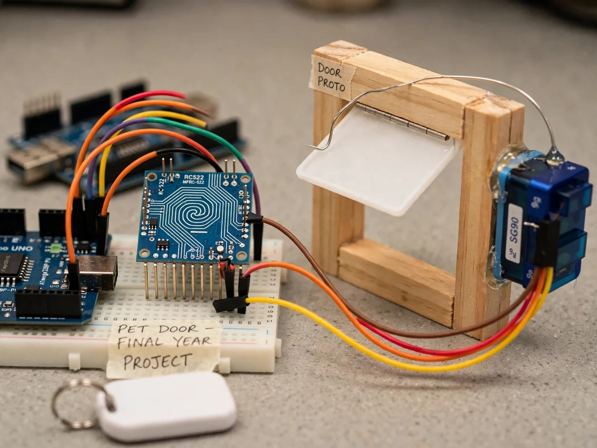
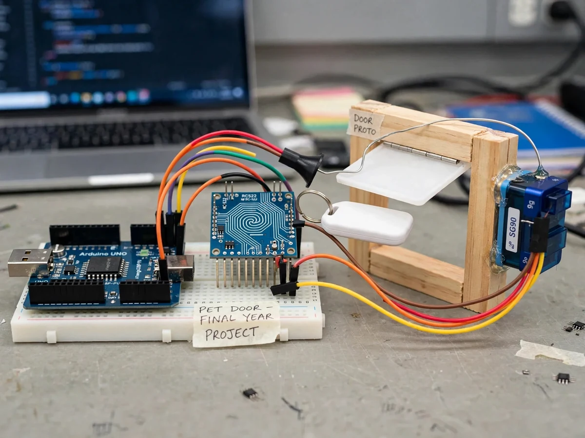
Pet doors are convenient and insecure in equal measure: a basic flap lets in any animal — and through a large flap, an intruder's hand. RFID access control solves the pet side of that problem the same way it secures office doors: only a registered credential opens the way. This project builds that idea with commodity parts. An Arduino Uno continuously polls an RC522 13.56 MHz RFID reader; when a tag is presented, its UID is compared against a registered list stored in the Arduino's EEPROM. A match drives an SG90 servo to swing the model door's flap open for a configurable hold time, then closes it; an unknown tag is simply ignored. Enrolling a new tag needs no PC — a documented button sequence puts the unit in enroll mode and the next presented tag is stored. The prototype is built at model scale on a wooden door frame, which keeps every mechanism visible and explainable for the report and viva. This is a built-to-order hardware project: the prototype is assembled, wired and tested fresh for your order.
How it works
- The RC522 reader continuously polls for 13.56 MHz tags within a few centimeters.
- When a tag is presented, the Arduino reads its UID over SPI.
- The UID is compared against the registered list stored in the Arduino's EEPROM.
- On a match, the SG90 servo rotates to swing the flap open; after the configured hold time it rotates back and the door closes.
- An unknown UID is ignored — the flap never moves — so unregistered animals (or tags) stay outside.
- Enrollment: a documented button sequence enters enroll mode, and the next presented tag's UID is written to EEPROM.
Tech stack:
- Arduino Uno R3 (ATmega328P)
- RC522 RFID reader module (13.56 MHz)
- SG90 micro servo motor
- MIFARE key fobs / cards (registered tags)
- Arduino IDE + MFRC522 library
- 5 V USB power supply
- Model wooden pet-door frame with flap
| Parameter | Value |
|---|---|
| Controller | Arduino Uno R3, ATmega328P @ 16 MHz |
| Reader | RC522, 13.56 MHz; design target read distance 2–5 cm |
| Tags | MIFARE 1K fobs/cards (UID-based check) |
| Actuator | SG90 servo, 180° rotation, ~1.8 kg·cm (datasheet) — model flap only |
| Registry | Arduino EEPROM; design target up to ~50 tag UIDs |
| Hold time | Configurable in firmware (seconds) |
| Power | 5 V USB |
| Connectivity | None — fully offline |
Project features
- [Tag-based access] Only registered MIFARE tag UIDs actuate the door; unknown tags are ignored and the flap stays shut.
- [Servo door actuation] An SG90 servo swings the flap open on a valid scan and returns it after a configurable hold time.
- [PC-free enrollment] New tags are registered with a documented button procedure and stored in EEPROM — no computer needed after setup.
- [Adjustable hold time] The open duration is a single firmware constant, tunable to the pet and door.
- [UID registry in EEPROM] Registered tags survive power cycles without re-enrollment.
- [Fully offline operation] No Wi-Fi, no cloud, no app — the entire access decision happens on the Arduino.
What is included
- Assembled and tested working prototype (Uno, RC522, SG90, model door frame)
- Complete firmware source code (reading, UID matching, servo control, enrollment)
- Circuit/wiring documentation with connection diagram
- Component list with sourcing notes
- Tag enrollment and testing procedure
- Project report PDF (background, methodology, test table of tag trials)
- PPT presentation for final review
- Viva Q&A preparation document (RFID, SPI, EEPROM, servo control)
Limitations & prerequisites
- The RC522's design-target read distance is only 2–5 cm — the tag must be presented close to the reader, which suits a pet collar tag but not walk-up detection.
- UID-only checking is not strong security: MIFARE Classic UIDs can be cloned, so this is pet convenience, not a high-security lock — the report states this openly.
- The SG90's ~1.8 kg·cm torque lifts the light model flap only; a real door needs a larger actuator (documented as future scope).
- The prototype is a model-scale demonstrator on a wooden frame, not a weatherproof installed pet door.
- EEPROM has limited write cycles (~100,000); enrollment is infrequent by design.
Frequently Asked Questions
Which controller is used?
An Arduino Uno R3. The firmware uses the MFRC522 library over SPI and stores registered UIDs in EEPROM.
How do I add a new tag?
With the documented button procedure — no PC needed. Enter enroll mode, present the new tag, and its UID is stored in EEPROM.
Does it need internet or Wi-Fi?
No — the entire access decision happens on the Arduino. It is fully offline.
Is it secure against intruders?
It is pet-grade, not high-security: UID-only checks can be cloned, and the report states this openly. It keeps unregistered animals out; it is not a burglar-proof lock.
What are the main limitations?
2–5 cm read range, clonable UIDs, model-scale servo torque, and no weatherproofing. Details are in Limitations & Prerequisites above.
Is this project suitable for a final-year project?
Yes — for IoT, Electronics and Computer programs. It demonstrates RFID, SPI communication, EEPROM storage and servo control with a testable, demo-friendly build. Suitable for B.E./B.Tech final-year projects in IoT, Electronics and Computer Engineering.
Components & software requirements
- Arduino Uno R3 (ATmega328P)
- RC522 RFID reader module (13.56 MHz)
- SG90 micro servo motor
- MIFARE key fobs / cards (registered tags)
- Arduino IDE + MFRC522 library
- 5 V USB power supply
- Model wooden pet-door frame with flap
Delivery information
Built-to-order project. Delivery timeline is shared after order confirmation based on current queue.
Support terms
Complete documentation, setup guide, and viva preparation included. Support for setup and explanation provided.