
More project photos (2)
The problem
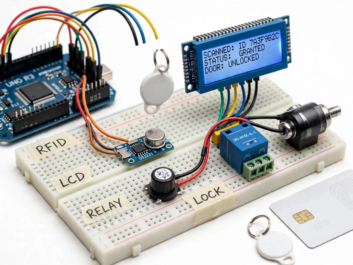
Colleges still mark attendance with paper registers that get lost, miscounted and fudged, while lab and classroom doors rely on shared keys that cannot track who entered or when. RFID cards solve both halves of this problem with one tap: the same card that opens the door also creates the attendance record. This project builds that combined system as an Arduino-based prototype. An RC522 reader at 13.56 MHz reads each card's UID, the Arduino compares it with the enrolled-student list stored on the board, and for valid cards it energizes a relay that releases a 12V solenoid door lock while the 20x4 LCD shows the student status. Every scan — granted or denied — is logged to a CSV file on a microSD card with the date and time from a DS3231 real-time clock, so the attendance register is generated automatically. A master card puts the unit into enrollment mode to register new cards, and a duplicate-swipe debounce ignores accidental re-taps.
Taps the RFID card or keyfob on the reader to request access.
Follow the working sequence
How it works
- The RC522 reader energizes its 13.56 MHz field and waits for a 13.56 MHz RFID card or keyfob to enter its read range (typically up to about 5 cm).
- On a tap, the module reads the card's UID over SPI and hands it to the Arduino Uno, which looks the UID up in the enrolled-student list stored in memory.
- For a matching UID, the firmware drives the relay module, which switches the separate 12V supply to the solenoid door lock and retracts the bolt for the configured unlock window.
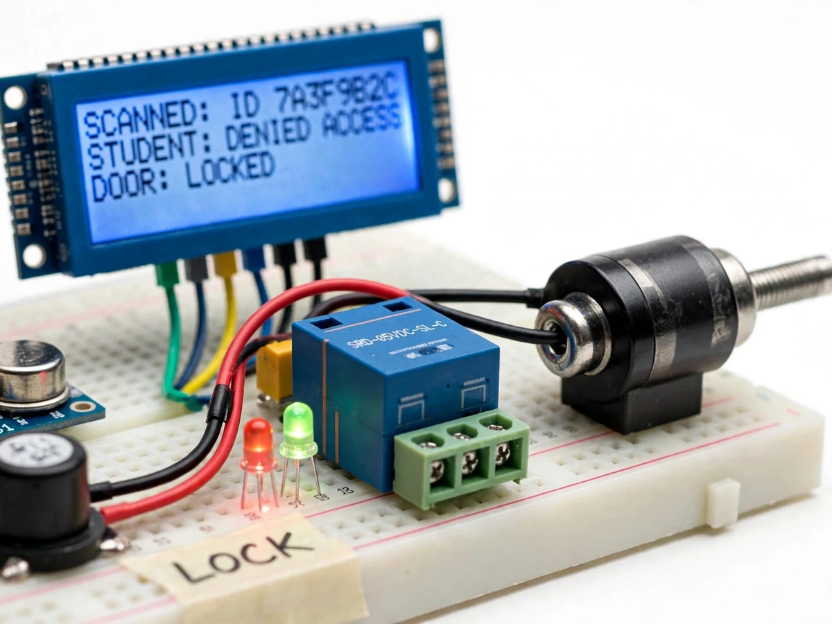
- The 20x4 LCD shows the scan result (SCANNED, GRANTED/DENIED, DOOR state), the green LED and buzzer confirm access, or the red LED and warning tone flag a denied card.
- Every event — card UID, date and time from the DS3231 RTC, granted or denied — is appended to a CSV attendance log on the microSD card and echoed on the serial monitor.
- In enrollment mode (entered by tapping the master card), tapped cards are added to the enrolled list; re-taps inside the debounce window are ignored to prevent duplicate rows.
Tech stack:
- Arduino Uno (ATmega328P) with Arduino IDE (C/C++) firmware
- RC522 RFID reader module (13.56 MHz, SPI)
- 20x4 character LCD with I2C backpack
- DS3231 real-time clock (I2C, battery-backed)
- Single-channel 5V relay module (SRD-05VDC-SL-C)
- 12V DC solenoid door lock
- MicroSD card module (SPI) with CSV logging
- Active buzzer and red/green status LEDs
| Parameter | Value |
|---|---|
| Controller | Arduino Uno, ATmega328P @ 16 MHz |
| RFID reader | RC522 module, 13.56 MHz, ISO14443A-compatible (MIFARE-classic cards/keyfobs), SPI |
| Read range | Typically up to about 5 cm, tag- and placement-dependent (not a measured claim) |
| Card UID | 4 / 7 / 10-byte UIDs supported |
| Display | 20x4 character LCD, I2C backpack, blue backlight |
| Real-time clock | DS3231, ±2 ppm (datasheet), CR2032 backup battery |
| Relay module | 5V single channel, SRD-05VDC-SL-C; contacts 10A @ 250 VAC / 10A @ 30 VDC (datasheet) |
| Door lock | 12V DC solenoid bolt lock, requires separate 12V ~1A supply |
| Log storage | microSD card, CSV lines: date, time, UID, granted/denied |
| Unlock window | Configurable in firmware (default 5 s) |
| Debounce window | Configurable in firmware (default 3 s), ignores same-card re-taps |
| Indication | Active buzzer 5V + red/green LEDs |
| Power | Arduino on 5V (USB or adapter); solenoid on its own 12V adapter — never from the Arduino |
Project features
- [RC522 RFID card reading] Reads 13.56 MHz MIFARE-compatible cards and keyfobs over SPI and extracts each card's UID for identification.
- [Enrolled-card door unlocking] On a UID match, the Arduino energizes a 5V relay for a configurable unlock window, releasing the 12V solenoid door lock.
- [20x4 LCD status display] Shows idle prompts, scanned UID, granted/denied status, door state and enrollment-mode instructions on a backlit LCD.
- [Master-card enrollment mode] A designated master card switches the unit into enrollment mode; tapping new cards adds their UIDs without touching code or a computer.
- [SD-card attendance logging] Every scan is appended to a CSV file (date, time, UID, result) on a microSD card, with timestamps from a battery-backed DS3231 RTC.
- [Granted/denied indication] Green LED and a short beep confirm access; unknown cards trigger the red LED, a warning tone and a denied message — the door stays locked.
- [Duplicate-swipe debounce] Re-taps of the same card inside the configurable debounce window are ignored, so one person cannot create duplicate attendance rows.
What is included
- Assembled working prototype: Arduino Uno, RC522 reader, 20x4 LCD, DS3231 RTC, relay module, solenoid door lock, buzzer, LEDs and sample RFID cards/keyfobs on breadboard
- Complete Arduino firmware (C/C++): scan, enroll, debounce, relay control, LCD UI, CSV logging
- Wiring diagram and pin-connection documentation
- MicroSD CSV log format with a sample attendance file
- Project report PDF (background, RFID theory, hardware design, methodology, results)
- PPT presentation for final review
- Viva Q&A preparation document (RFID, SPI/I2C, relay interfacing, RTC, access-control logic)
- Downloadable project abstract PDF
Limitations & prerequisites
- RC522 reads 13.56 MHz tags at only a few centimetres; metal surfaces or a fast wave-past can miss a tap — present the card steadily.
- Standard MIFARE-classic UIDs can be cloned, so this is an academic access-control demonstrator, not a high-security door system.
- The 12V solenoid draws its current from a separate adapter (~1A); it must never be powered from the Arduino's 5V pin or USB.
- The relay switches the low-voltage lock only; never wire mains or heavy loads through it — contact rating is 10A at 250 VAC per datasheet.
- Logging is local on the microSD card; there is no network, cloud dashboard or remote alerts in the base build.
- The DS3231 must be time-set once during setup (procedure included); its CR2032 battery keeps time when power is off.
- Breadboard prototype is a classroom/lab demonstrator, not a weatherproof or industrial door controller.
Frequently Asked Questions
Which RFID technology does it use?
The RC522 reader works at 13.56 MHz and reads ISO14443A-compatible cards and keyfobs (the common MIFARE-classic cards). Cards operating at 125 kHz (EM4100-style) are not compatible with this reader.
How does the master-card enrollment mode work?
Tapping the designated master card puts the unit into enrollment mode, shown on the LCD. Tapping a new card then adds its UID to the enrolled list; tapping the master card again exits the mode. No computer or code changes are needed.
What happens if the same card is tapped twice quickly?
The firmware's duplicate-swipe debounce ignores re-taps of the same UID inside the configured window (default 3 seconds), so one student cannot generate duplicate attendance rows by waving the card.
What exactly is logged, and where?
Each scan appends one CSV line — date, time, card UID and granted/denied result — to the microSD card, using the battery-backed DS3231 for timestamps. The log also streams on the serial monitor for live demos.
Does it need internet or a computer to run?
No. The system runs fully offline on the Arduino; the enrolled list lives on the board and logs go to the SD card. A computer is only used for the initial firmware upload and for reading the CSV file afterwards.
Is this project suitable for a final-year project?
Yes — for Electronics, Electronics & Telecommunication, Electrical and IoT & Embedded programs. It demonstrates RFID communication, SPI/I2C peripheral interfacing, relay power interfacing, real-time logging and a complete access-control workflow, all explainable in a viva. Suitable for B.E./B.Tech final-year projects in Electronics, Electronics & Telecommunication, Electrical and IoT & Embedded.
Components & software requirements
- Arduino Uno (ATmega328P) with Arduino IDE (C/C++) firmware
- RC522 RFID reader module (13.56 MHz, SPI)
- 20x4 character LCD with I2C backpack
- DS3231 real-time clock (I2C, battery-backed)
- Single-channel 5V relay module (SRD-05VDC-SL-C)
- 12V DC solenoid door lock
- MicroSD card module (SPI) with CSV logging
- Active buzzer and red/green status LEDs
Delivery information
Built-to-order project. Delivery timeline is shared after order confirmation based on current queue.
Support terms
Complete documentation, setup guide, and viva preparation included. Support for setup and explanation provided.
Download free synopsis (PDF)
Enter your name and email — the synopsis PDF downloads immediately. We may send occasional project updates; no spam, unsubscribe anytime.