
More project photos (3)
The problem
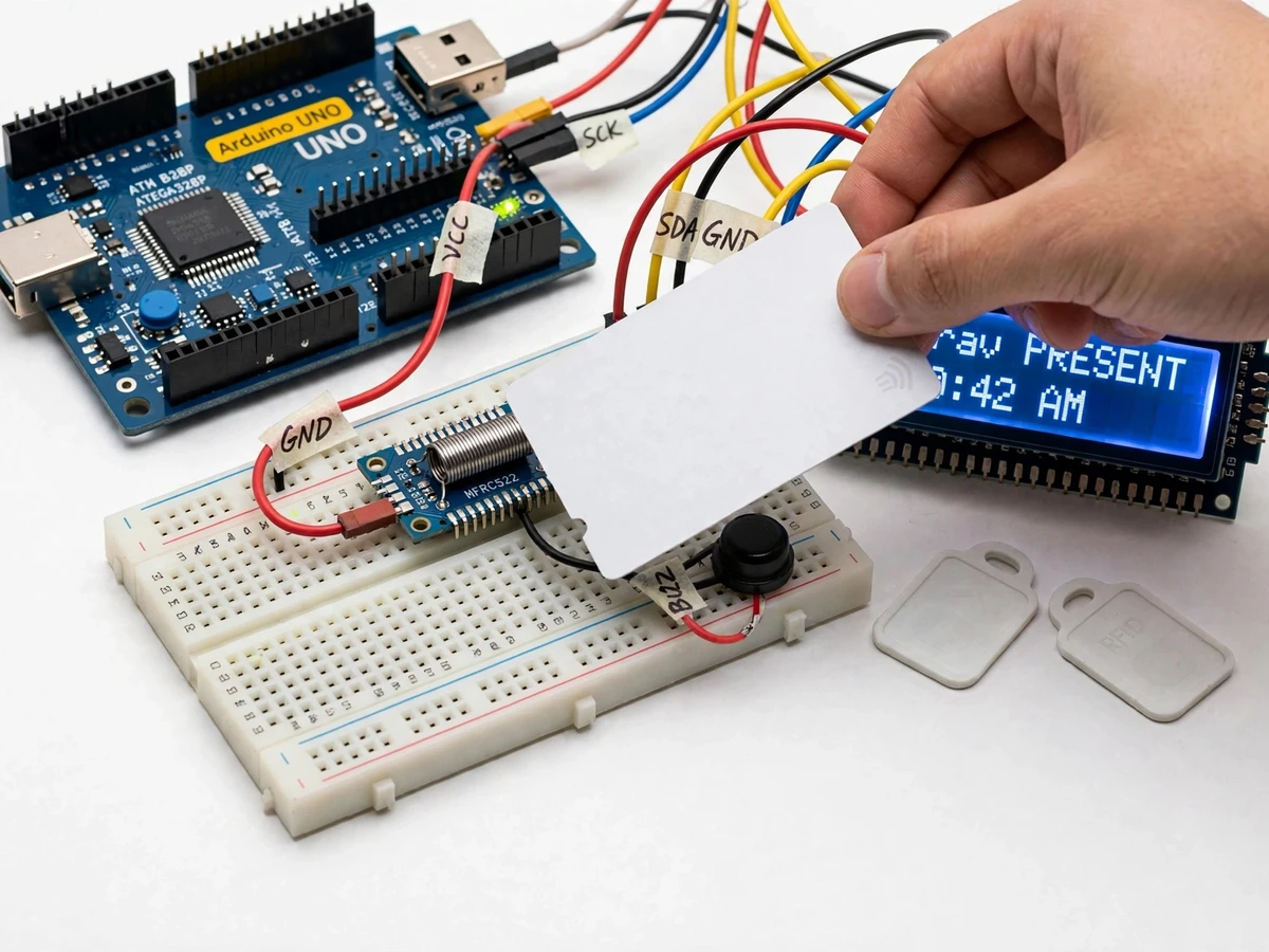
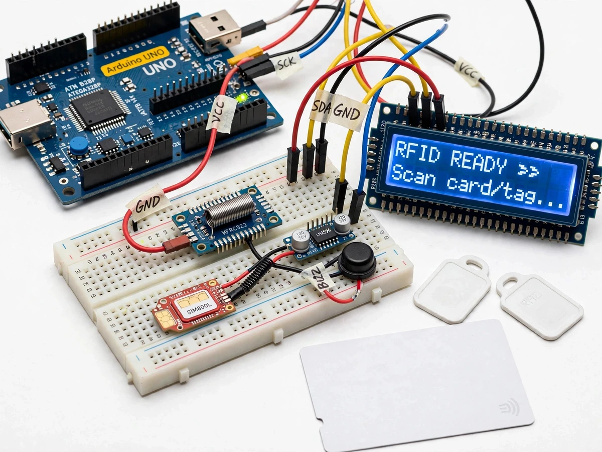
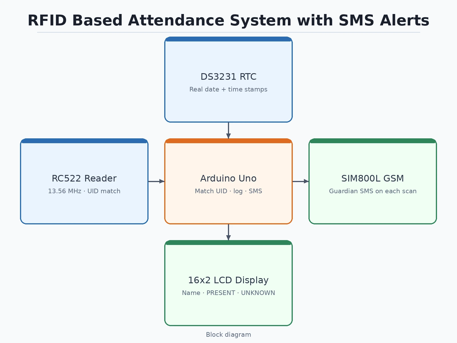
Paper attendance registers are slow, easy to fudge, and invisible to parents: a student can be marked present by a friend, and the guardian finds out about absences only when it is too late to matter. Electronic attendance systems exist, but most student-built versions stop at a reader and an LCD — they never close the information loop with the one party who actually cares whether the student showed up. This project builds the full loop. Each student taps a MIFARE card on the RC522 reader; the firmware matches the card's factory-burned UID against an enrolled list, stamps the entry with the date and time from a real-time clock, shows the student's name on the LCD — and a SIM800L GSM module sends an SMS to the enrolled guardian number within the same scan cycle. The day's log exports over USB serial as a CSV the student can open in a spreadsheet. Every part of the pipeline — SPI card reading, AT-command SMS, RTC timekeeping, EEPROM enrollment storage — is built and explained in the report, so the student can defend each subsystem in the viva.
How it works
- The student taps their MIFARE card on the RC522 antenna; the reader powers the tag through its 13.56 MHz field (datasheet) and reads the factory-burned 4-byte UID (datasheet).
- The Arduino Uno compares the UID byte-for-byte against the enrolled list held in its 1 KB EEPROM (datasheet) — approximately 200 slots (design target).
- On a match, the firmware reads the date and time from the DS3231 RTC (datasheet) and writes the entry — student name, date, time — into the day's attendance log.
- The 16x2 LCD (HD44780, I2C backpack) displays the student's name and PRESENT while the buzzer gives the accepted tone.
- In the same scan cycle, the SIM800L transmits an SMS to the enrolled guardian number using AT commands (AT+CMGF=1, AT+CMGS) at 9600 baud (design), over the GSM quad-band network (datasheet: 850/900/1800/1900 MHz).
- An unknown UID triggers the rejection path instead: LCD shows UNKNOWN CARD, the buzzer sounds the rejected pattern, and nothing is logged or sent.
- At day end, the operator triggers the log dump over USB serial; the CSV exports name, date, time and SMS status per entry for records and the report.
Tech stack:
- Arduino Uno (ATmega328P)
- MFRC522 RFID reader module (13.56 MHz)
- SIM800L GSM module (AT-command SMS)
- DS3231 real-time clock module
- 16x2 LCD with I2C backpack · 5 V buzzer
- MIFARE Classic 1K cards/tags (4-byte UID)
- LM2596 buck converter (4 V rail for the GSM module)
- Arduino IDE firmware (C/C++)
| Parameter | Value |
|---|---|
| Controller | Arduino Uno: ATmega328P, 16 MHz, 5 V logic, 32 KB flash, 1 KB EEPROM (all datasheet) |
| RFID reader | MFRC522 module, 13.56 MHz carrier, SPI interface, 3.3 V supply (all datasheet) |
| Read range | Approximately 5 cm with the stock PCB antenna (datasheet-typical) |
| Cards | MIFARE Classic 1K: 4-byte UID, 1024-byte EEPROM (datasheet) |
| GSM module | SIM800L: 3.4–4.4 V supply (datasheet), peak approximately 2 A during transmit bursts (datasheet-typical) |
| GSM bands | Quad-band 850/900/1800/1900 MHz (datasheet); SMS via AT commands at 9600 baud (design) |
| Real-time clock | DS3231: approximately ±2 ppm accuracy (datasheet), CR2032 backup cell |
| Display | 16x2 HD44780 LCD via I2C (PCF8574) backpack |
| Enrollment capacity | Approximately 200 UIDs in 1 KB EEPROM (design target) |
| SMS content | Configurable text template with name + timestamp fields (design) |
| Power | 5 V adapter for logic; separate 4 V / 2 A-capable rail for the SIM800L (design) |
Project features
- [Tap-and-mark attendance] The RC522 reader energizes each MIFARE card at 13.56 MHz (datasheet) and reads its 4-byte factory-burned UID at a read range of approximately 5 cm (datasheet-typical); matching is byte-for-byte against the enrolled list, so the reader never "learns" a card — it compares numbers.
- [Guardian SMS on every scan] A SIM800L GSM module sends a text ("
marked present at - [RTC-stamped daily log] A DS3231 real-time clock (approximately ±2 ppm, datasheet) stamps every entry with real date and time. Builder note: the Uno has no clock of its own — without the RTC every timestamp is just millis() since boot; the RTC is what makes this an attendance log instead of a counter.
- [On-device enrollment] New cards are enrolled from the keypad-and-LCD flow: tap an unregistered card, assign the student name and guardian number to its UID slot. Approximately 200 UIDs fit the Uno's 1 KB EEPROM (design target: 4-byte UID plus a slot flag per record).
- [LCD and buzzer feedback] The 16x2 LCD shows the student's name and PRESENT on a valid scan, or UNKNOWN CARD on rejection; a 5 V active buzzer gives distinct short/long patterns for accepted, rejected and enrolled events.
- [Unknown-card rejection] UIDs not in the enrolled list are refused outright — no log entry, no SMS, LCD and buzzer signal the rejection. A lost card can be de-enrolled from its slot.
- [USB log export] The day's log (name, date, time, SMS status) dumps over USB serial as CSV, ready to open in a spreadsheet or paste into the report appendix.
What is included
- Fully wired and tested prototype (Arduino Uno, RC522 reader, SIM800L, DS3231, LCD, buzzer, cards and tags)
- Complete Arduino firmware source with comments
- Circuit diagram and breadboard wiring documentation
- Enrollment, SMS-template configuration and log-export procedure
- Project report PDF (RFID principles, UID matching, GSM AT-command flow, RTC timekeeping, testing procedure)
- PPT presentation for final review
- Viva Q&A preparation document (SPI, MIFARE UID structure, AT commands, EEPROM storage, power design)
Limitations & prerequisites
- SMS needs an active SIM with SMS balance on a live GSM network; with no network there is no SMS, though the attendance log still records.
- The RC522 reads one tag per tap at approximately 5 cm (datasheet-typical) — waving a stack of cards does not mark everyone at once.
- Enrollment tops out at approximately 200 UIDs in the Uno's 1 KB EEPROM (design target); a whole college would need the SD-card extension listed under future scope.
- SMS delivery typically takes 5–15 seconds per message (network-typical, not a guarantee); messages are queued in firmware, not promised instant.
- The SIM800L must run on its own 4 V / 2 A-capable supply (datasheet: 3.4–4.4 V, approximately 2 A bursts). Builder note: sharing the Uno's 5 V rail browns out the board on transmit bursts — the separate supply with a common ground is the single most common fix for random "SMS not sent" failures.
- MIFARE Classic UIDs are clonable, so the UID check stops casual misuse, not a determined cloner — this is an academic attendance prototype, not a security product.
Frequently Asked Questions
How does the SMS part actually work?
The SIM800L is a GSM modem: the Arduino talks to it over serial with AT commands (AT+CMGF=1 to select text mode, AT+CMGS to send). It needs a normal active SIM with SMS balance — no internet, no Wi-Fi, no app. Each accepted scan fires one message to the guardian number stored against that card's UID slot.
Does it need internet or a computer running?
No. Everything runs on the Arduino: the reader, clock, LCD and GSM module are all local hardware. The only time a computer is involved is the optional end-of-day CSV export over USB.
How many students can it handle?
Approximately 200 enrolled cards in the Uno's 1 KB EEPROM (design target). That covers a class or a lab batch; scaling to a full college would mean moving the enrollment list to an SD card, which is listed as future scope.
What happens if two cards are tapped at once, or a stranger's card is used?
One card per tap — the reader resolves the strongest tag in its approximately 5 cm field (datasheet-typical). A UID that is not in the enrolled list is rejected: the LCD shows UNKNOWN CARD, the buzzer signals rejection, and nothing is logged or texted.
Is this project suitable for a final-year project?
Yes — for Electronics, E&TC and Electrical programs. It demonstrates SPI interfacing with the RC522, the MIFARE UID structure, AT-command control of a GSM modem, real-time clock timekeeping, and EEPROM data storage in one working system, with every subsystem tunable and measurable by the student.
Components & software requirements
- Arduino Uno (ATmega328P)
- MFRC522 RFID reader module (13.56 MHz)
- SIM800L GSM module (AT-command SMS)
- DS3231 real-time clock module
- 16x2 LCD with I2C backpack · 5 V buzzer
- MIFARE Classic 1K cards/tags (4-byte UID)
- LM2596 buck converter (4 V rail for the GSM module)
- Arduino IDE firmware (C/C++)
Delivery information
Built-to-order project. Delivery timeline is shared after order confirmation based on current queue.
Support terms
Complete documentation, setup guide, and viva preparation included. Support for setup and explanation provided.
Download free synopsis (PDF)
Enter your name and WhatsApp number — the synopsis PDF downloads immediately. We may send occasional project updates on WhatsApp; no spam.