
More project photos (2)
The problem
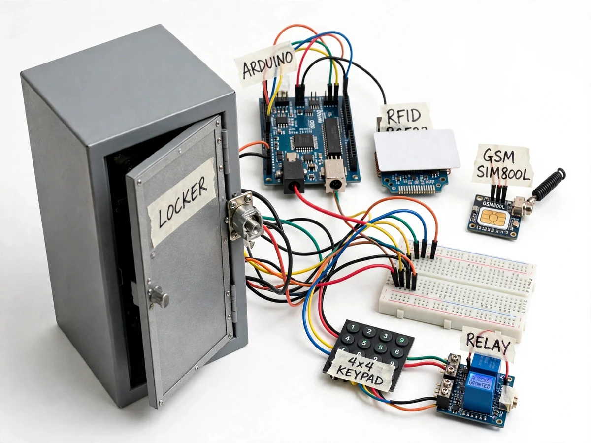
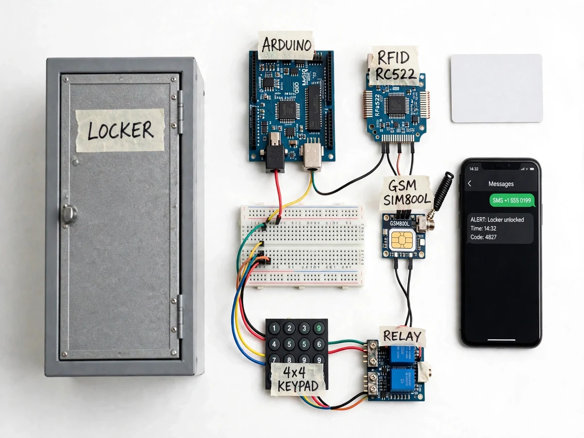
Bank lockers still rely on a physical key, so a lost or copied key is enough to open a locker, and the owner learns about the access only after the loss is discovered. The Bank Locker Security System using RFID and GSM replaces the single key with two checks: an RC522 RFID card and a 4x4 keypad PIN, both verified by an Arduino Uno before a 12 V solenoid lock releases the model locker door. Every attempt, successful or failed, is shown on a 16x2 LCD and sent as an SMS alert through a SIM800L GSM module to the owner's phone, so an unauthorised attempt is reported the moment it happens instead of days later. The build is a model-scale demonstration locker, not a certified bank-grade security system, and it shows how access control, event logging and remote alerts work together in one embedded system. GSM alerts depend on network coverage and a valid SIM card.
The user holds an RFID card flat against the RC522 reader.
Follow the working sequence
How it works
The Bank Locker Security System using RFID and GSM works as one continuous chain from card tap to lock release and alert. A user holds an RFID card against the RC522 reader, which powers the tag by inductive coupling at 13.56 MHz and reads its unique ID over SPI. The Arduino Uno compares that ID against the authorised list in its 1 KB EEPROM, then asks for the 4-digit PIN on the 4x4 keypad as a second check. Only when both the card and the PIN match does the Arduino switch the relay module, which energises the 12 V solenoid lock for a few seconds to release the door. Meanwhile the 16x2 LCD shows the result, the event is written to the serial log, and the SIM800L GSM module sends an SMS alert to the owner's phone. A wrong card, a wrong PIN, or 3 failed attempts in a row keeps the locker locked and sends a failed-access alert instead.
- The user holds an RFID card or key fob flat against the RC522 reader, within approximately 5 cm of the antenna.
- The RC522 powers the passive tag by inductive coupling at 13.56 MHz and reads its unique ID over the SPI bus.
- The Arduino Uno compares the UID with the authorised list stored in its 1 KB EEPROM and shows the result on the 16x2 LCD.
- If the card is authorised, the LCD prompts for the 4-digit PIN, entered on the 4x4 membrane keypad.
- When the card and the PIN both match, the Arduino switches the relay module, energising the 12 V solenoid lock for 5 seconds (design target) so the door can be opened.
- The LCD shows the outcome, the event is written to the serial log, and the SIM800L sends an SMS alert to the owner's phone using AT commands over UART.
- After 3 consecutive failed attempts the locker stays locked, the LCD shows an access-denied message, and a failed-access SMS alert is sent.
Tech stack:
- Arduino Uno (ATmega328P)
- RC522 RFID module (MFRC522)
- SIM800L GSM module
- 4x4 membrane keypad
- 12 V solenoid lock · relay module
- 16x2 LCD display
- Arduino IDE · C/C++
- MFRC522 library · SoftwareSerial
| Parameter | Value |
|---|---|
| Controller | Arduino Uno (ATmega328P, 16 MHz clock speed, 5 V operating voltage) |
| RFID reader | RC522 module (NXP MFRC522, 13.56 MHz frequency, ISO/IEC 14443A standard) |
| RFID read distance | Up to 50 mm (datasheet value; approximately 5 cm in practice) |
| RFID interface | SPI, up to 10 Mbit/s (datasheet value) |
| RFID supply | 3.3 V (2.5–3.6 V operating range, datasheet value) |
| RFID current | 13–26 mA (datasheet value) |
| GSM module | SIM800L, quad-band 850/900/1800/1900 MHz |
| GSM supply | 3.4–4.4 V (4.0 V recommended, datasheet value) |
| GSM peak current | Up to 2 A during transmission bursts (datasheet value) |
| GSM interface | UART with AT commands |
| Lock | 12 V DC solenoid lock, approximately 0.5–1 A current draw (typical range) |
| Keypad | 4x4 membrane keypad, 16 keys |
| Display | 16x2 character LCD |
| Authorised cards | Up to 10 cards (design target, EEPROM storage) |
| PIN length | 4 digits |
| Unlock window | 5 seconds (design target) |
| SMS retry | Up to 3 attempts (implemented firmware behaviour) |
| Power | 12 V DC, 2 A adapter (recommended) |
| Locker | Model-scale demonstration locker, approximately 30 cm x 20 cm x 20 cm (design target) |
Project features
The Bank Locker Security System using RFID and GSM combines four capabilities in one Arduino build: two-factor access control, instant SMS alerts, a visible access log, and a fail-secure lock. Two-factor access means the locker opens only when an authorised RFID card and the matching 4-digit PIN are both presented, so a stolen card alone is not enough. The SIM800L GSM module sends an SMS on every access attempt, successful or failed, and the firmware retries a failed SMS up to 3 times before giving up and recording the failure in the log. A 16x2 LCD shows the current state at the locker, while the Arduino serial log records each event with its result for demonstration and viva discussion. The 12 V solenoid lock stays locked when power is lost, so the locker fails secure rather than springing open.
- [RFID + PIN two-factor access] The locker opens only after an authorised RFID card UID and the matching 4-digit PIN are both verified by the Arduino Uno. (Implemented)
- [GSM SMS alerts with retry] The SIM800L sends an SMS to the owner's phone on every access attempt, and retries a failed SMS up to 3 times before logging the failure. (Implemented)
- [16x2 LCD status display] The display shows each step — card accepted, enter PIN, access granted, access denied — so the demonstration is easy to follow. (Implemented)
- [Serial access log] Every attempt is recorded in the Arduino serial log with its card UID, PIN result and outcome for review and viva discussion. (Implemented)
- [Fail-secure solenoid lock] The 12 V solenoid lock stays locked when power is lost, and is energised only for a short unlock window after a successful check. (Implemented)
- [Card enrolment via master card] Authorised card UIDs are stored in the Arduino EEPROM and enrolled with a master card procedure, so cards can be added or removed without rewriting the firmware. (Implemented)
- [Buzzer alarm on failed attempts] A buzzer sounds after repeated failed attempts, drawing attention to a possible unauthorised try at the locker. (Optional customization)
Future scope (not included in the base build): fingerprint authentication, a cloud-based access log, and a mobile app for remote lock control.
What is included
- Working model-scale locker prototype with solenoid lock, RFID reader, keypad, GSM module and LCD
- Arduino firmware (source code) with RFID, PIN, GSM alert and logging logic
- Circuit and wiring documentation with pin connections
- Component list with part numbers
- Setup and demonstration instructions
- Project abstract PDF
- Project report, presentation slides and viva Q&A document
Limitations & prerequisites
- This is a model-scale demonstration locker, not a certified bank-grade security system; the metal box and solenoid lock are not rated against forced entry.
- RFID cards are matched by UID only; a cloned card carrying a copied UID would be accepted, since UID matching is not cryptographic authentication.
- GSM alerts need 2G network coverage and a valid SIM card with SMS balance; alerts are delayed or lost where coverage is weak.
- The RC522 read distance is up to 50 mm (datasheet value); cards must be held flat and close to the reader, and metal near the antenna shortens the range.
- The solenoid lock draws approximately 0.5–1 A and must be driven through the relay module; it is rated for intermittent use of a few seconds, not continuous energising.
- There is no battery backup in the base build; on power loss the locker stays locked (fail-secure) and alerts stop until power returns.
Frequently Asked Questions
How does the locker decide who can open it?
The locker opens only when two checks both pass: an authorised RFID card UID recognised by the RC522 reader, and the matching 4-digit PIN entered on the 4x4 keypad. A card alone cannot open it, and a PIN alone cannot open it either. The authorised UIDs are stored in the Arduino EEPROM, and the check runs entirely on the Arduino Uno.
What happens when someone tries the wrong card or PIN?
The locker stays locked, the LCD shows an access-denied message, the failed attempt is written to the serial log, and the SIM800L sends a failed-access SMS alert to the owner's phone. After 3 consecutive failed attempts the system keeps the locker locked and still sends the alert. The optional buzzer can also sound on repeated failures.
Does it need internet or Wi-Fi?
No, it needs neither internet nor Wi-Fi, because alerts travel as SMS over the 2G GSM network through the SIM800L module to the owner's phone. A valid SIM card with SMS balance, 2G network coverage and an active mobile plan is enough for the alerts to arrive. The Arduino, RFID reader, keypad and lock all work offline; only the SMS alert depends on the mobile network.
What power supply does it need?
A 12 V DC, 2 A adapter is recommended, because the solenoid lock draws approximately 0.5–1 A when it energises and the SIM800L can draw up to 2 A in short transmission bursts. The Arduino runs from its own 5 V USB or barrel-jack supply, and the SIM800L must have its own regulated 3.4–4.4 V feed, never the Arduino 5 V pin.
Can more cards be added or the PIN be changed?
Yes, up to 10 authorised cards (design target) can be enrolled using the master card procedure, and the PIN can be changed in the firmware configuration. Enrolled UIDs are stored in the Arduino EEPROM, so they survive a power cycle. Removing a lost card is done by re-enrolling the authorised set without that card.
Is this project suitable for a final-year project?
Yes, for Electronics and Telecommunication, Electrical and Computer Engineering programs. It demonstrates embedded C programming, SPI and UART communication, RFID and GSM interfacing, relay-driven actuation and two-factor access control in a single working prototype with a clear live demonstration for the review. The demonstration is easy to run live, and the limitations make honest viva discussion points.
Components & software requirements
- Arduino Uno (ATmega328P)
- RC522 RFID module (MFRC522)
- SIM800L GSM module
- 4x4 membrane keypad
- 12 V solenoid lock · relay module
- 16x2 LCD display
- Arduino IDE · C/C++
- MFRC522 library · SoftwareSerial
Delivery information
Built-to-order project. Delivery timeline is shared after order confirmation based on current queue.
Support terms
Complete documentation, setup guide, and viva preparation included. Support for setup and explanation provided.
Download free synopsis (PDF)
Enter your name and WhatsApp number — the synopsis PDF downloads immediately. We may send occasional project updates on WhatsApp; no spam.