
More project photos (2)
The problem
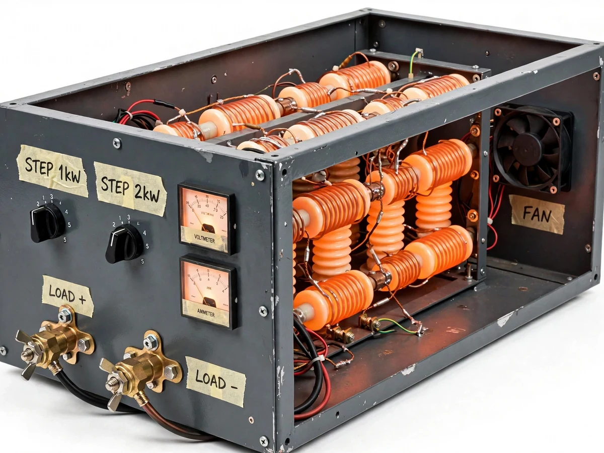
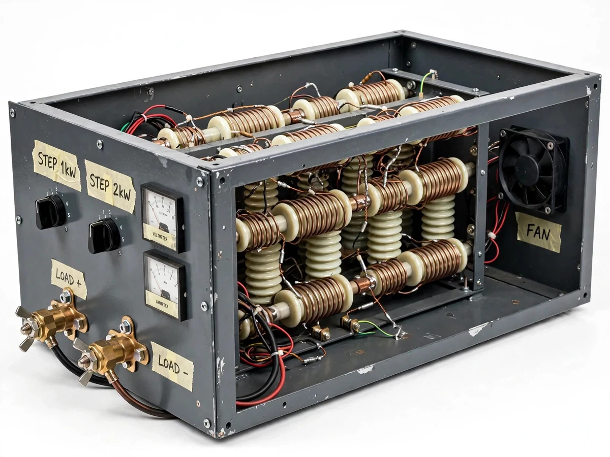
A generator is only proven when it is loaded — voltage regulation, frequency stability and thermal behaviour under step loads are the acceptance tests every generating set must pass, and the instrument that performs them is the load bank. Electrical students study regulation curves in machines theory but rarely apply a real, measured load to a real generator and watch the governor and AVR respond. This project builds that instrument: a ventilated steel enclosure housing banks of nichrome-wire heating elements on ceramic insulators, switched in binary-ish steps by front-panel rotary switches, with analog voltmeter and ammeter on the panel and a cooling fan for continuous duty. Connected to a small generator or the lab's test supply, the student switches load steps in sequence, records voltage and current at each step, plots the regulation curve, and performs a step-load transient observation — a genuine machines-lab experiment on student-built hardware.
How it works
- The load bank is connected to the generator under test (or the lab's variable test supply) through the heavy-duty terminals, with all step switches off.
- The generator is started and brought to rated voltage and frequency at no load; the no-load voltage is recorded from the panel voltmeter.
- Load step 1 is switched in; after the readings settle, voltage and current are recorded, and the generator's recovery is observed.
- Further steps are switched in one at a time, recording V and I at each step up to the bank's rated load.
- The student plots the voltage regulation curve (terminal voltage versus load current) from their own readings.
- One step is switched off suddenly and the voltage overshoot and recovery are observed and described, demonstrating transient response qualitatively.
- The thermal behaviour is logged over a timed continuous run, and the cool-down procedure is followed before shutdown.
Tech stack:
- Ventilated MS enclosure with element mounting frame
- Nichrome heating-element banks on ceramic insulators
- Heavy-duty rotary step-load switches
- Analog panel voltmeter and ammeter (instrument spec)
- Cooling fan with thermal cutout interlock
- Brass terminal lugs and high-temperature wiring
- Step-load test procedure manual
- Regulation-curve workbook and fabrication drawings
| Parameter | Value |
|---|---|
| Load type | Resistive (unity power factor) heating-element banks |
| Load steps | Approximately 1 kW + 2 kW sections, combinable to ~5 kW (design target) |
| Rated voltage | 230 V single-phase AC (design target) |
| Metering | Panel voltmeter + ammeter, analog (instrument spec) |
| Cooling | Forced-air fan with thermal cutout (design target) |
| Enclosure | Ventilated MS, approximately 600 × 400 × 400 mm (design target) |
| Test output | Regulation curve from student V/I readings (procedure) |
Project features
- [Stepped resistive load banks] Nichrome heating elements on ceramic insulators are grouped into switched steps (e.g. 1 kW + 2 kW sections), so load is applied in known, repeatable increments.
- [Front-panel step switching] Heavy-duty rotary switches on the panel engage each load step independently — the student feels the generator respond to each switching event.
- [Panel voltmeter and ammeter] Analog panel meters read load voltage and current directly, so every regulation reading is a real instrument observation.
- [Forced-air cooling] A cooling fan ventilates the enclosure for continuous-duty runs, with the thermal design explained in the report.
- [Heavy-duty terminations] Brass terminal lugs and high-temperature wiring handle the load current safely, demonstrating proper high-current construction practice.
- [Step-load test procedure] A written procedure takes the student from no-load through stepped loading to the regulation curve and the transient observation.
- [Thermal safety interlock] A thermal cutout disconnects the load banks on over-temperature, and the manual enforces the cool-down discipline.
What is included
- Complete resistive load bank (assembled and tested)
- Step-load test procedure manual
- Regulation-curve workbook with plotting sheets
- Thermal run log sheets
- Fabrication and wiring drawings
- Project report PDF (theory, procedure, readings, analysis)
- PPT presentation for final review
- Viva Q&A preparation document (regulation, load banks, generator response, safety)
Limitations & prerequisites
- The bank is purely resistive (unity power factor); reactive-power and power-factor loading tests need a different (inductive) bank, noted as future scope.
- The ~5 kW rating suits small generators and lab test supplies; it cannot load-test large commercial DG sets.
- Transient response is observed qualitatively on the panel meters; capturing the exact waveform needs an oscilloscope or recorder, listed as an extension.
- Element resistance drifts slightly with temperature; the report explains hot-vs-cold resistance and why readings are taken at settled temperature.
- Continuous full-load runs need the cool-down discipline in the manual; the thermal cutout is a backup, not the operating procedure.
Frequently Asked Questions
What does the student actually measure?
Terminal voltage and load current at each load step — the regulation curve is plotted entirely from these readings.
What generator can it test?
Small single-phase generators and portable DG sets up to the bank's ~5 kW rating, or the lab's variable AC test supply.
Why a resistive bank and not just heaters?
It is a bank of heaters — but switched in calibrated steps, metered, cooled and thermally protected, which is what makes it a test instrument rather than a room heater.
Is it safe?
The design includes an earthed metal enclosure, thermal cutout, high-temperature wiring and a written operating procedure; the manual's safety section is mandatory reading before first use.
What goes into the report?
Load-bank theory and construction, the step-load procedure, the measured regulation curve, transient observations, thermal run data and conclusions.
Is this project suitable for a final-year project?
Yes — for Electrical programs. It is a real test instrument performing the standard generator acceptance test with measured results. Suitable for B.E./B.Tech final-year projects in Electrical Engineering.
Components & software requirements
- Ventilated MS enclosure with element mounting frame
- Nichrome heating-element banks on ceramic insulators
- Heavy-duty rotary step-load switches
- Analog panel voltmeter and ammeter (instrument spec)
- Cooling fan with thermal cutout interlock
- Brass terminal lugs and high-temperature wiring
- Step-load test procedure manual
- Regulation-curve workbook and fabrication drawings
Delivery information
Built-to-order project. Delivery timeline is shared after order confirmation based on current queue.
Support terms
Complete documentation, setup guide, and viva preparation included. Support for setup and explanation provided.