
More project photos (2)
The problem
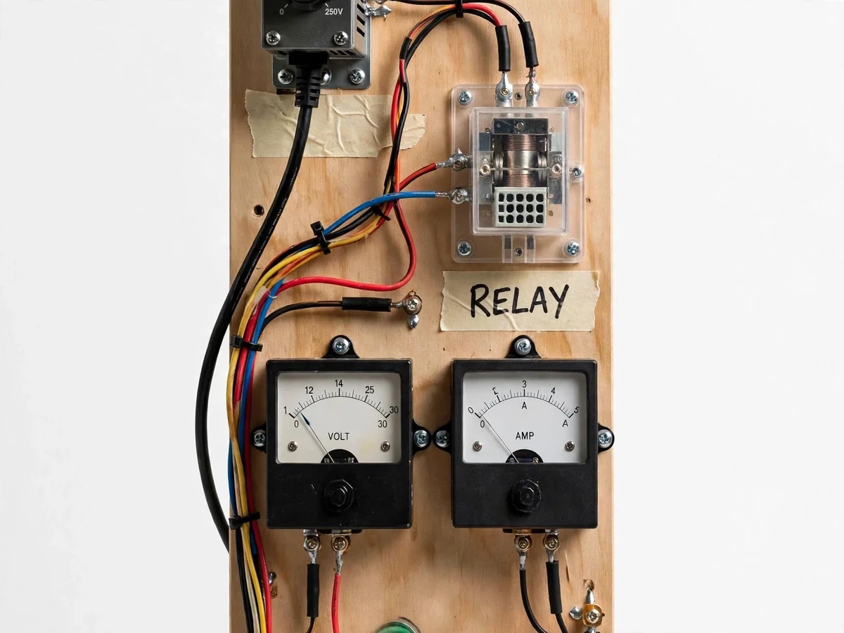
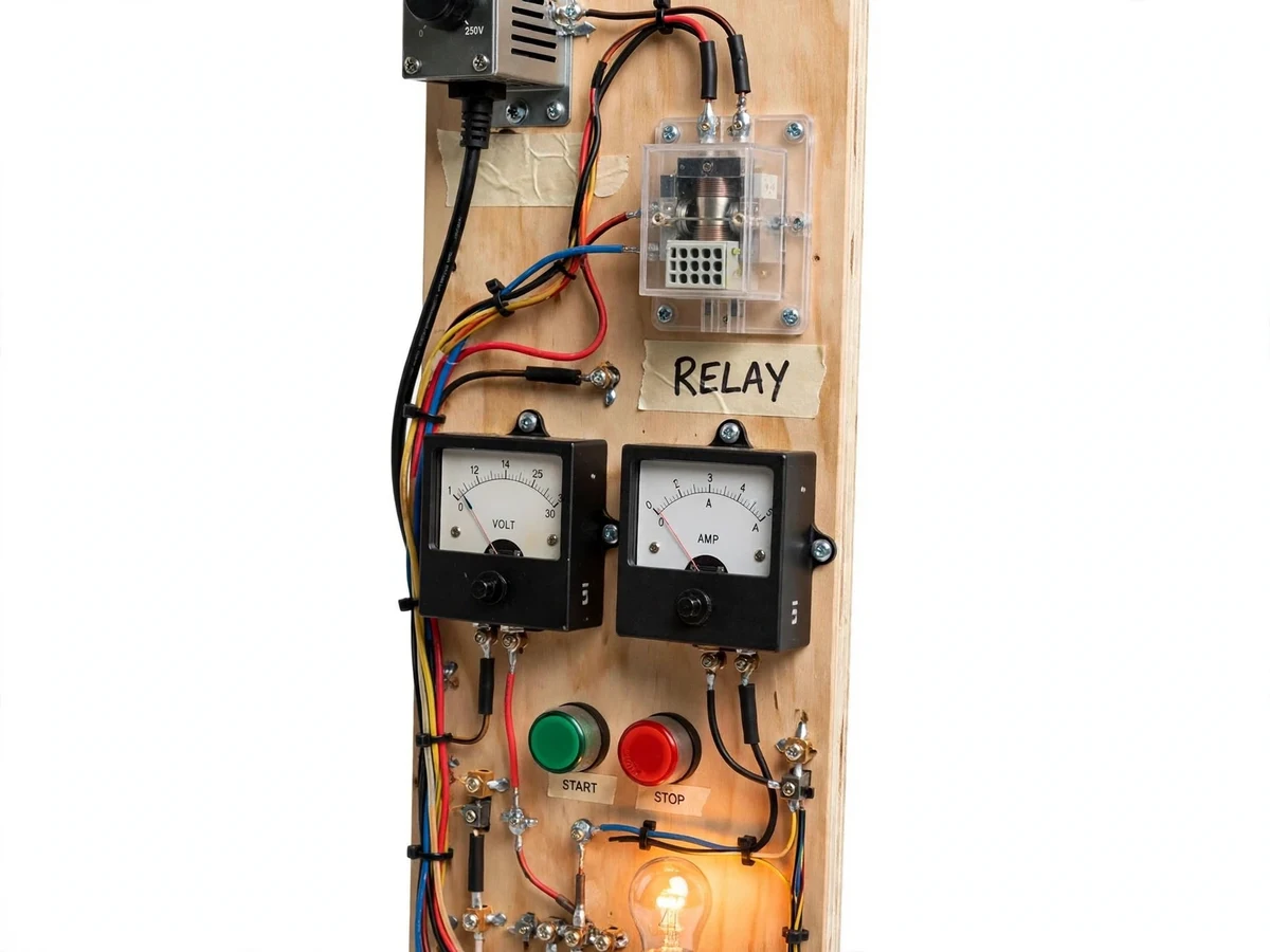
Every protection scheme — from a motor starter's overload relay to a substation's protection panel — depends on one humble device behaving predictably: the electromagnetic relay must pick up at its set voltage and drop out cleanly below it, every time. Students draw relay symbols and contact logic in switchgear-and-protection theory, but the physical reality of pickup voltage, dropout ratio, contact bounce and operating time stays invisible inside sealed relays. This project opens it up: a bench test panel with a small autotransformer (variac) feeding a plug-in electromagnetic relay mounted in a transparent socket, panel voltmeter and ammeter on the coil circuit, start/stop push buttons and a lamp load on the contacts. The student raises the voltage slowly to find pickup, lowers it to find dropout, computes the dropout ratio, times the operation, and verifies NO/NC contact logic — the complete characteristic test of a protection relay, measured by hand.
How it works
- The relay is plugged into its transparent socket and the coil circuit is wired through the variac, voltmeter and ammeter per the panel diagram.
- With the variac at zero, the supply is switched on and the voltage is raised slowly while watching the relay armature.
- The voltmeter reading at the instant the armature pulls in is recorded as the pickup voltage; the run is repeated three times and averaged.
- The voltage is then lowered slowly from above pickup; the reading at the instant the armature releases is recorded as the dropout voltage, again averaged over repeats.
- The dropout ratio (dropout ÷ pickup) is computed and compared with the typical range discussed in the theory section.
- The NO/NC lamps are observed through a full operate-release cycle to verify contact logic, and the operating time is measured with the stopwatch procedure.
- All readings feed the characteristic table and the analysis section of the report.
Tech stack:
- Wooden/steel bench test panel with component layout
- Plug-in electromagnetic relay in transparent socket
- Small autotransformer (variac) 0–270 V (design target)
- Panel voltmeter and ammeter (instrument spec)
- Start/stop push buttons and indicator lamp load
- NO/NC contact wiring with terminal blocks
- Stopwatch for operating-time procedure
- Characteristic workbook and wiring diagram
| Parameter | Value |
|---|---|
| Relay | Plug-in electromagnetic, transparent socket (design) |
| Test supply | Variac 0–270 V AC (design target) |
| Metering | Panel voltmeter + ammeter on coil circuit (instrument spec) |
| Measurements | Pickup voltage, dropout voltage, dropout ratio, operating time |
| Contact demo | NO/NC contacts to indicator lamps (design) |
| Procedure | Step-up/step-down with 3-repeat averaging (procedure) |
| Panel | Bench panel, approximately 450 × 350 mm (design target) |
Project features
- [Transparent-socket relay] A plug-in electromagnetic relay in a clear socket exposes the coil, armature and contacts, so pickup and dropout are visible as well as measurable.
- [Variac test supply] A small autotransformer gives smooth 0–270 V (design) adjustment, letting the student approach pickup and dropout gradually for precise readings.
- [Coil-circuit metering] Panel voltmeter and ammeter on the relay coil circuit record the exact electrical conditions at pickup and dropout.
- [Pickup/dropout procedure] A written step-up/step-down procedure with repeat runs gives statistically honest pickup and dropout values, not single lucky readings.
- [Contact-logic demo] NO and NC contacts wired to indicator lamps show the contact changeover at the instant of operation — protection logic made visible.
- [Operating-time measurement] A stopwatch-based procedure times pull-in, giving the student a real (approximate) operating-time figure to discuss.
- [Dropout-ratio analysis] The workbook computes the dropout-to-pickup ratio and discusses its meaning for protection coordination.
What is included
- Complete relay characteristic test rig (assembled and tested)
- Electromagnetic relay in transparent socket (plus one spare)
- Variac and panel meters wired on the panel
- Characteristic measurement workbook
- Wiring diagram and panel layout drawing
- Project report PDF (theory, procedure, readings, analysis)
- PPT presentation for final review
- Viva Q&A preparation document (pickup/dropout, relay construction, protection basics)
Limitations & prerequisites
- The rig characterizes one small control relay type; it does not replicate IDMT overcurrent or distance-relay characteristics (a numerical relay trainer covers those).
- Pickup/dropout are read by eye on analog meters while turning the variac, so readings carry typical ±1–2 V operator error — the repeat-and-average procedure addresses this honestly.
- Operating time is measured with a stopwatch procedure (approximate, ~0.1 s resolution), not a digital timer — the report states the method's limits.
- The variac output is mains-derived; the manual's safety rules (one-hand probing, insulated terminals) are mandatory.
- Contact-life or endurance testing is out of scope; the rig is for characteristic measurement, not relay qualification.
Frequently Asked Questions
What does the student actually measure?
The exact voltages at which the relay picks up and drops out (averaged over repeats), the dropout ratio, the operating time, and the NO/NC contact behaviour.
Why does the dropout ratio matter?
Protection relays must not chatter near the threshold; the ratio quantifies the clean release margin, and the report discusses what values are acceptable.
Can the relay be seen working?
Yes — the transparent socket shows the armature pulling in and dropping out, synchronized with the meter readings and the lamp changeover.
Is this related to the overcurrent relay trainer?
It complements it: this rig studies the fundamental electromechanical relay characteristic, while a numerical overcurrent trainer studies IDMT curves.
Is mains involved?
The variac runs from mains, so the panel is built with shrouded terminals and the manual enforces strict safety rules; the relay coil side stays at low test voltages.
Is this project suitable for a final-year project?
Yes — for Electrical programs. It converts protection-theory terms into measured relay characteristics on a proper test panel. Suitable for B.E./B.Tech final-year projects in Electrical Engineering.
Components & software requirements
- Wooden/steel bench test panel with component layout
- Plug-in electromagnetic relay in transparent socket
- Small autotransformer (variac) 0–270 V (design target)
- Panel voltmeter and ammeter (instrument spec)
- Start/stop push buttons and indicator lamp load
- NO/NC contact wiring with terminal blocks
- Stopwatch for operating-time procedure
- Characteristic workbook and wiring diagram
Delivery information
Built-to-order project. Delivery timeline is shared after order confirmation based on current queue.
Support terms
Complete documentation, setup guide, and viva preparation included. Support for setup and explanation provided.