
More project photos (3)
The problem
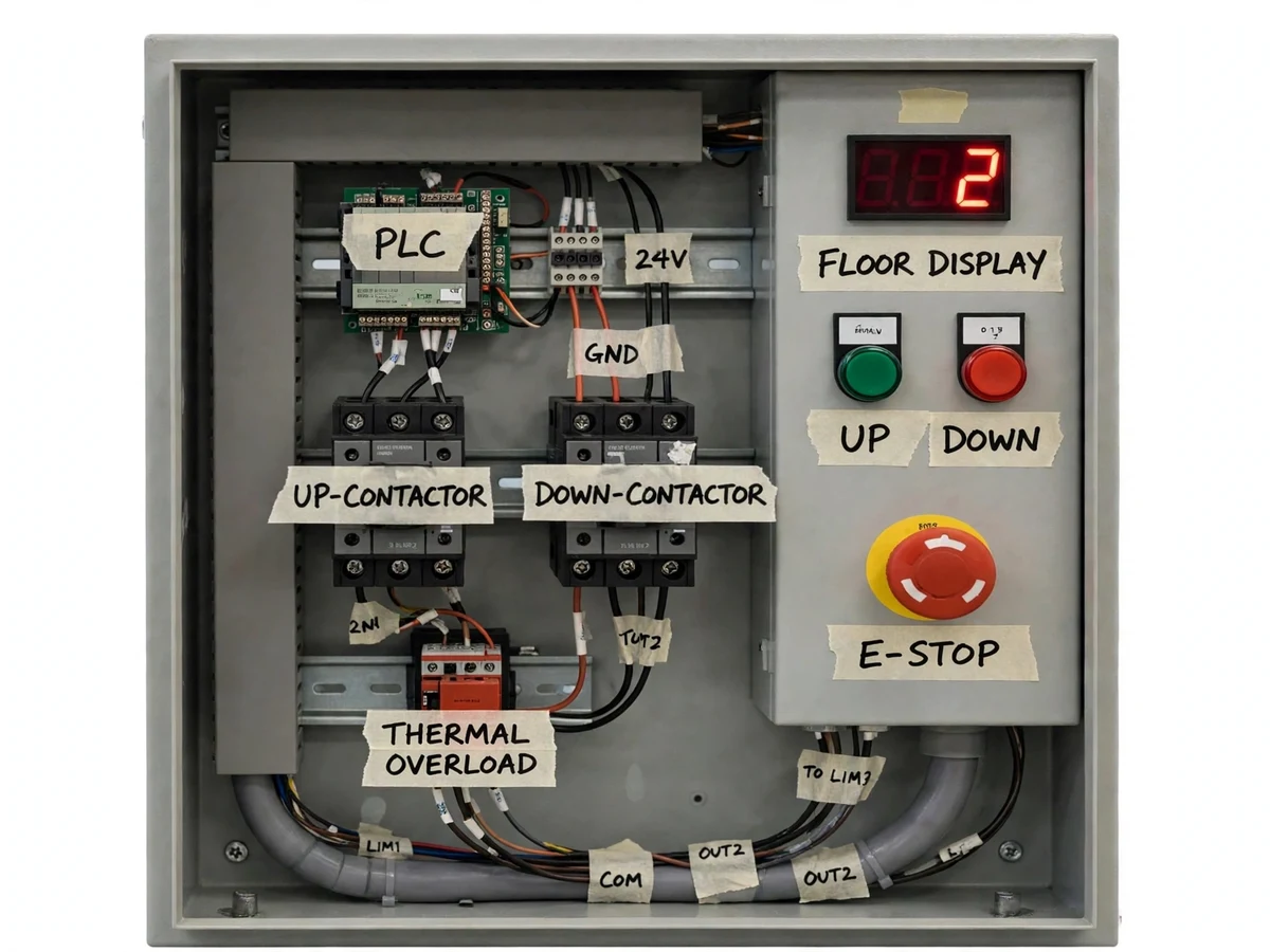
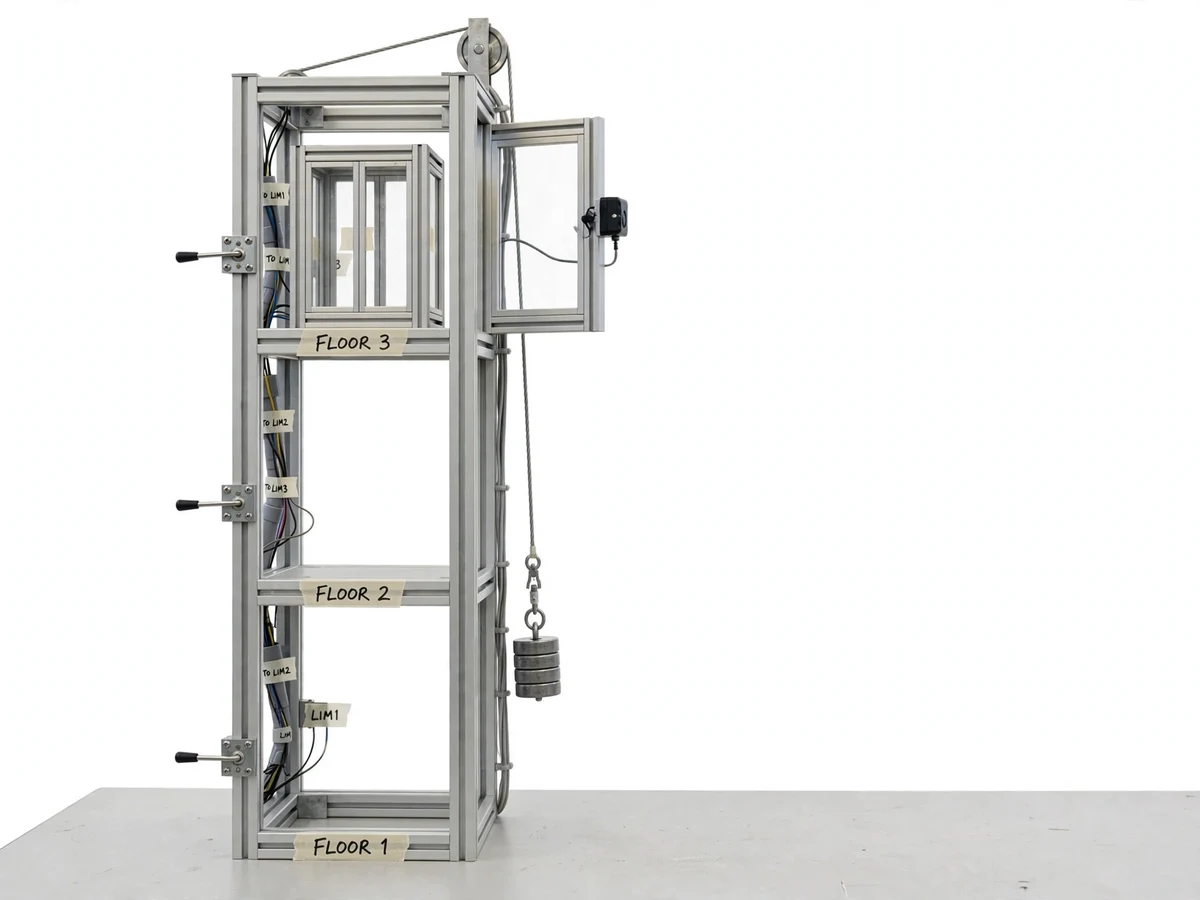
Elevators are among the most familiar industrial control systems, yet the PLC ladder logic behind them is usually taught only in theory. Most students learn PLC programming on simulators, where a wrong rung costs nothing — they never wire a real contactor, never see an overload relay trip, and never design a safety chain that must fail safe in hardware. This project builds a scaled 3-floor elevator model controlled by a Delta-class PLC: floor calls are queued in ladder logic with collective-control priority, a contactor-based reversing starter drives the car, limit switches and a proximity sensor confirm position at each floor, a 7-segment display shows the current floor, and a door interlock plus a hardwired emergency stop form a safety chain that works independently of software. The build closes the gap between classroom ladder diagrams and the industrial panel — wiring, commissioning and troubleshooting a real, moving machine.
Normally-open push buttons at the three landings and inside the car feed the PLC digital inputs.
Follow the working sequence
How it works
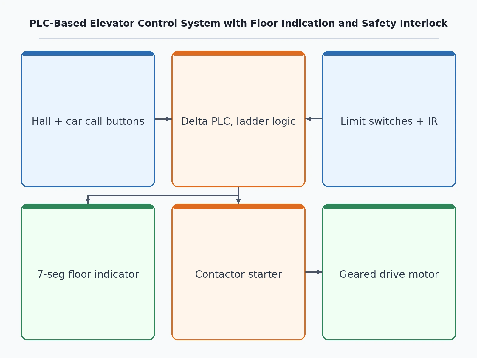
- Call buttons at the three landings and inside the car (normally-open push buttons) feed the PLC's digital inputs; the ladder program stores each request as a latched bit in the call queue.
- The queue logic picks the next destination using collective control: the car continues serving calls in its current travel direction and reverses only when no calls remain ahead.
- The PLC energizes the up or down contactor of the reversing starter; NC auxiliary contacts cross-interlock the two contactors so they can never close simultaneously, and the motor accelerates the car direct-on-line.
- At each floor, limit switches and an inductive proximity sensor confirm the car's arrival; the PLC de-energizes the contactor, stopping the car level with the landing.
- A 7-segment display driven by the PLC's outputs shows the floor number derived from the sensor-confirmed position, updating only when arrival is verified.
- Door logic runs independently of motion: the door may open only when the car is at a floor; an IR obstruction sensor reopens the door if the path is blocked, and travel is blocked until the door is closed and latched.
- The emergency stop is hardwired as a NC contact in series with the contactor coil circuit — pressing it drops the motor drive even if a PLC output sticks on; the thermal overload relay trips on overcurrent and requires manual reset.
Tech stack:
- Delta DVP-14SS class PLC (8 DI / 6 DO) with ladder logic
- AC contactors with NC auxiliary cross-interlock + thermal overload relay
- Geared drive motor with contactor reversing starter
- Limit switches + inductive proximity sensor per landing
- IR obstruction sensor (door safety)
- Common-anode 7-segment floor indicator
- 230 V AC control supply + 24 V DC I/O supply
- DIN-rail control panel, wiring ducts, labeled terminals
| Parameter | Value |
|---|---|
| Controller | Delta DVP-14SS class PLC, 8 digital inputs / 6 digital outputs (datasheet value) |
| Floors served | 3 (scaled model, design choice) |
| Drive motor | Geared motor with contactor-based reversing starter (design choice) |
| Contactor coil | 230 V AC (datasheet value) |
| Car travel speed | Approximately 0.05 m/s (design target, scaled model) |
| Limit-switch repeat accuracy | Approximately ±1 mm (design target) |
| Floor indicator | Single 7-segment display, common-anode (design choice) |
| Emergency stop | NC mushroom button, hardwired in contactor coil circuit (design choice) |
| Overload relay setting | Set per motor nameplate FLA (buyer-configured during commissioning) |
| Power supplies | 230 V AC control supply; 24 V DC for sensors and indicators (design values) |
Project features
- [Ladder-logic floor-call queueing] Hall and car calls enter a priority queue implemented as ladder rungs with latching bits; the car serves the nearest pending call in its current travel direction before reversing (collective control), the same scheme real elevators use.
- [Contactor-based motor reversing starter] Two interlocked contactors switch the drive motor for up and down travel, with NC auxiliary contacts cross-wired so both contactors can never close at once, plus a thermal overload relay on the motor circuit.
- [7-segment floor position indication] A common-anode 7-segment display shows the current floor, driven from sensor-confirmed car position rather than just the commanded state, so the indicator always reflects reality.
- [Fail-safe door interlock with IR obstruction sensing] The door opens only when the car is at a floor; an IR sensor reopens the door if the path is blocked and blocks travel until the door is fully closed and latched.
- [Hardwired emergency stop and overload protection] A NC mushroom E-stop sits in series with the contactor coil circuit, dropping the motor drive regardless of PLC state; the overload relay trips on overcurrent and locks out until manually reset.
- [Per-floor position feedback] Limit switches and an inductive proximity sensor at each landing confirm car arrival, letting the ladder logic stop the car level with the floor and flag missed stops.
- [Manual/auto selector with jog mode] A selector switch offers automatic run, manual jog for wiring tests and commissioning, and a fault-reset position after overload or E-stop trips.
What is included
- Working scaled 3-floor elevator model with PLC control panel
- PLC ladder-logic program (source) with rung-by-rung comments
- Wiring schematic and terminal-connection documentation
- Component list with specifications
- Project report PDF (background, methodology, wiring, test procedure, results)
- PPT presentation for final review
- Viva Q&A preparation document
- Demonstration and commissioning guidance
Limitations & prerequisites
- Scaled demonstration model: car speed (approximately 0.05 m/s design target) and payload are for lab demonstration and cannot be compared with commercial elevators.
- Direct-on-line contactor starting — no variable-frequency drive, so there is no smooth speed ramping or precise leveling curve.
- Position feedback comes from discrete limit switches and proximity sensors, not an absolute encoder; it cannot report continuous shaft position.
- The unit is an academic demonstration model, not certified to any lift-safety code, and must never carry passengers.
- The base build serves 3 floors; more floors need additional PLC I/O, buttons, sensors and panel space (quoted as customization).
- PLC brand and part numbers may vary with availability; wiring and terminal assignments follow the unit actually built and shipped.
Frequently Asked Questions
Which PLC is used and why?
A Delta DVP-14SS class small PLC (8 digital inputs, 6 outputs) — the standard teaching-industry class for ladder logic. An equivalent small PLC with the same I/O count can be substituted with availability; the ladder program structure (queue bits, interlock rungs, door logic) carries across brands.
Is the emergency stop software-controlled?
No, deliberately. The E-stop is a NC mushroom button wired in series with the contactor coil circuit, so pressing it drops the motor drive even if a PLC output module fails or the ladder logic faults. This hardware-first safety chain is exactly how real industrial panels are wired.
Can the model be extended to more floors?
Yes, as a customization. Each added floor needs extra call buttons, landing sensors and PLC inputs; the ladder queue logic scales to more floors, but the PLC's 8 DI / 6 DO limit and panel space set a practical ceiling — typically 4–5 floors in this class.
What power supply does it need?
Standard 230 V AC single-phase mains for the contactor coils and motor circuit, plus a 24 V DC supply for the PLC I/O, sensors and the floor indicator. No three-phase supply and no internet or Wi-Fi is needed — the panel runs fully offline.
What will I receive with the project?
The working scaled elevator model with PLC panel, commented ladder-logic source, wiring schematic and component list, plus the documentation kit: project report PDF, review PPT and viva Q&A. Commissioning and demonstration guidance is included.
Is this project suitable for a final-year project?
Yes — for Electrical Engineering (and E&TC/Instrumentation) programs. It demonstrates PLC ladder programming, motor reversing starters, industrial panel wiring, sensor-based position feedback and hardware-level safety design — the core skills of industrial automation.
Components & software requirements
- Delta DVP-14SS class PLC (8 DI / 6 DO) with ladder logic
- AC contactors with NC auxiliary cross-interlock + thermal overload relay
- Geared drive motor with contactor reversing starter
- Limit switches + inductive proximity sensor per landing
- IR obstruction sensor (door safety)
- Common-anode 7-segment floor indicator
- 230 V AC control supply + 24 V DC I/O supply
- DIN-rail control panel, wiring ducts, labeled terminals
Delivery information
Built-to-order project. Delivery timeline is shared after order confirmation based on current queue.
Support terms
Complete documentation, setup guide, and viva preparation included. Support for setup and explanation provided.
Download free synopsis (PDF)
Enter your name and email — the synopsis PDF downloads immediately. We may send occasional project updates; no spam, unsubscribe anytime.