
More project photos (2)
The problem
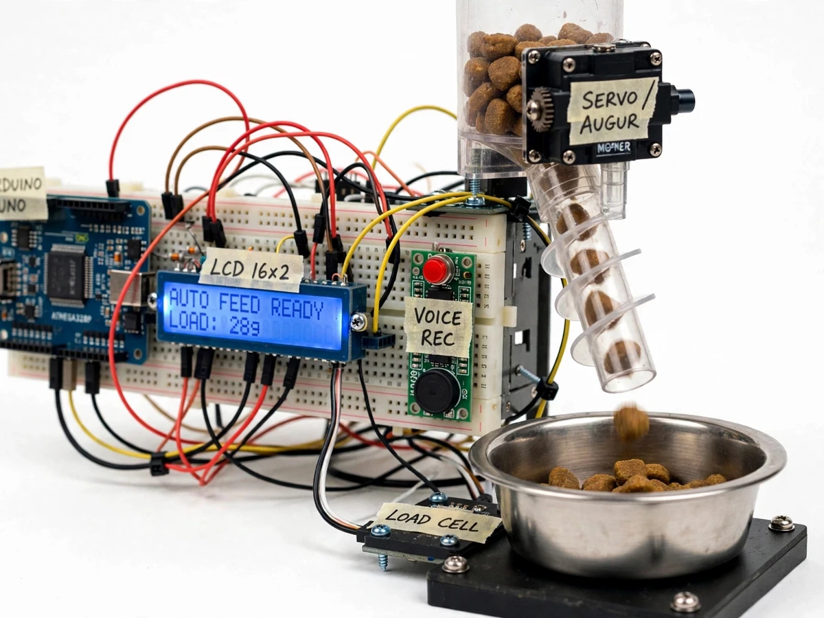
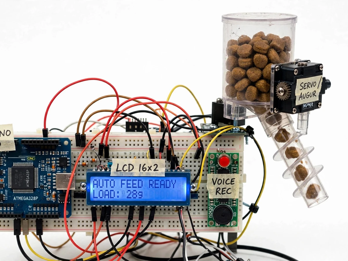
Working pet owners face a daily tug-of-war: leaving for college or the office early, getting home late, and still needing the dog or cat fed at the same times in the same amounts. Commercial automatic feeders exist, but the affordable ones dose food by running a motor for a fixed time — so the portion silently changes as the hopper level drops and kibble flows differently, and over weeks the pet is over- or under-fed. Owners also notice that a disembodied bowl filling at random doesn't call the pet the way a familiar voice does. This project fixes both gaps with a closed-loop design: the Arduino weighs every portion on a load cell as it dispenses, so the weight is correct regardless of hopper level or kibble shape, and an on-board voice module plays the owner's own recorded call at each feeding. The result is a genuinely working prototype with measurable engineering — timing accuracy, weighing resolution and repeatable portions — and a viva story built on real subsystems rather than a black-box gadget.
Tracks time of day; coin cell keeps schedules through outages.
Follow the working sequence
How it works
- The DS3231 RTC (datasheet accuracy ±2 ppm) tracks time of day, backed by a CR2032 cell so schedules survive mains outages; up to 3 feed times live in EEPROM.
- At each scheduled time, the Arduino triggers the ISD1820 voice module, which plays the owner's recorded 10-second voice call through its on-board speaker.
- The Arduino then drives the MG996R servo (9.4 kgf·cm stall torque at 4.8 V, datasheet value) to rotate the auger, metering dry kibble from the approximately 1.5 L hopper into the steel bowl.
- While dispensing, the HX711 (24-bit ADC, datasheet value) samples the load cell under the bowl several times per second; firmware tares the bowl weight and accumulates only the added food.
- The moment the weighed portion reaches the user-set target (design range 10–100 g), the servo stops — closed-loop control keeps portions consistent regardless of hopper fill or kibble shape.
- The 16x2 LCD reports "FEED DONE", the served weight and the next scheduled time; if the measured weight stops rising mid-dispense, the buzzer sounds a refill alert for the empty hopper.
Tech stack:
- Arduino Uno (ATmega328P)
- DS3231 real-time clock module
- HX711 24-bit ADC + strain-gauge load cell
- MG996R servo + auger dispenser
- ISD1820 voice record/playback module
- 16x2 LCD with I2C backpack
- EEPROM + push-button setup UI
- Arduino IDE (C/C++ firmware)
| Parameter | Value |
|---|---|
| Portion range | 10–100 g per feed (design target) |
| Hopper capacity | Approximately 1.5 L, approx 1.2 kg dry kibble (design target) |
| Feed schedules | Up to 3 per day, stored in EEPROM |
| RTC accuracy | ±2 ppm (datasheet value, DS3231) |
| Clock backup | CR2032 cell, approx 3 years backup (datasheet value) |
| Servo stall torque | 9.4 kgf·cm at 4.8 V (datasheet value, MG996R) |
| Load-cell ADC | 24-bit (datasheet value, HX711) |
| Voice recording | 10 s maximum (datasheet value, ISD1820) |
| Display | 16×2 character LCD |
| Supply | 7–12 V DC via Arduino barrel jack (datasheet value); separate 5 V servo feed recommended (design) |
| Kibble | Dry kibble, 5–15 mm diameter (design target) |
Project features
- [Weight-based portion control] An HX711 24-bit ADC reads a strain-gauge load cell under the bowl continuously during dispensing; the servo auger stops the instant the target portion is reached, so portions are correct whatever the hopper level.
- [RTC-scheduled automatic feeding] A DS3231 real-time clock (datasheet accuracy ±2 ppm) with CR2032 backup keeps up to 3 daily feed times stored in Arduino EEPROM, surviving power cuts.
- [Recordable voice call] An ISD1820 voice module records the owner's own message (10 s maximum, datasheet value) through its on-board microphone and plays it through the speaker at every scheduled feeding.
- [Servo-driven auger dispenser] An MG996R servo (9.4 kgf·cm stall torque at 4.8 V, datasheet value) rotates the auger to meter dry kibble from the hopper into the bowl.
- [16x2 LCD status display] Shows current time, next scheduled feed, live bowl weight and feeding state, all driven over I2C.
- [Manual feed and refill alarm] A push button dispenses one feed on demand; if the weight stops rising during a dispense, a buzzer and LCD message signal an empty hopper.
- [Simple button-based setup] Feed times and portion targets are configured with three push buttons and the LCD — no phone app or computer needed after flashing.
What is included
- Assembled and tested Arduino pet-feeder prototype (hopper, auger, servo, load cell, bowl, LCD, voice module, buttons)
- Arduino firmware (C/C++) with documented RTC scheduling, HX711 weighing and ISD1820 playback code
- Wiring diagram and pin-mapping table
- Load-cell calibration guide (buyer calibrates with a known 100 g weight)
- Portion-setting and voice-recording user manual
- Project report PDF (background, working principle, circuit and firmware design, test results)
- PPT presentation for final review
- Viva Q&A preparation document (RTC accuracy, closed-loop weighing, servo drive, voice module, calibration)
Limitations & prerequisites
- Built for dry kibble of 5–15 mm diameter (design target); wet food, sticky treats or fine powder can jam the auger.
- Portion accuracy depends on load-cell calibration: uncalibrated, ±5–10 g drift is possible (expected); calibrating with a known 100 g weight brings error under ±2 g (design target).
- The approximately 1.2 kg hopper limits unattended operation to roughly 10–20 days at 3 feeds of 30–50 g per day (expected).
- The ISD1820 records at most 10 s (datasheet value) in analog quality — a familiar call, not studio audio.
- On mains loss the clock keeps time on battery backup but dispensing stops; there is no cloud or app alert — an Arduino-only design by intent.
- A pet shoving the bowl hard mid-feed can disturb the weighing; firmware waits 3 s of settled readings before stopping the servo.
- Load cells drift slightly with temperature; keep the unit indoors and re-tare between calibrations for best repeatability.
Frequently Asked Questions
How does the portion control actually work?
The bowl sits on a strain-gauge load cell read by a 24-bit HX711 ADC. During every feed the Arduino weighs the bowl live and stops the servo auger the moment the target weight is reached — a closed loop, so hopper level and kibble shape cannot silently change the portion.
How is the voice call recorded?
The ISD1820 module has an on-board microphone and record button: hold the button, speak the call (up to 10 s, datasheet value), release, and the message is stored in the chip's non-volatile memory. It plays automatically at every scheduled feed and survives power loss.
How long does the clock survive a power cut?
The DS3231 carries a CR2032 backup cell (approximately 3 years, datasheet value). Time and feed schedules are preserved through outages; only dispensing pauses until mains return.
What happens if the hopper runs empty?
During a dispense the firmware watches the weight curve: if the weight stops rising while the auger is still running, it stops the servo and sounds the buzzer with an "EMPTY" message on the LCD.
Can it feed more than three times a day?
The default firmware supports 3 daily schedules, which covers typical pet routines; the schedule slots are a firmware constant that can be extended on request.
Is this project suitable for a final-year project?
Yes — for Electronics, E&TC and Embedded programs. It combines RTC-based scheduling, 24-bit ADC interfacing, closed-loop weight control, servo actuation and an embedded user interface, all measurable in the demo and defensible in the viva.
Components & software requirements
- Arduino Uno (ATmega328P)
- DS3231 real-time clock module
- HX711 24-bit ADC + strain-gauge load cell
- MG996R servo + auger dispenser
- ISD1820 voice record/playback module
- 16x2 LCD with I2C backpack
- EEPROM + push-button setup UI
- Arduino IDE (C/C++ firmware)
Delivery information
Built-to-order project. Delivery timeline is shared after order confirmation based on current queue.
Support terms
Complete documentation, setup guide, and viva preparation included. Support for setup and explanation provided.
Download free synopsis (PDF)
Enter your name and email — the synopsis PDF downloads immediately. We may send occasional project updates; no spam, unsubscribe anytime.