
More project photos (2)
The problem
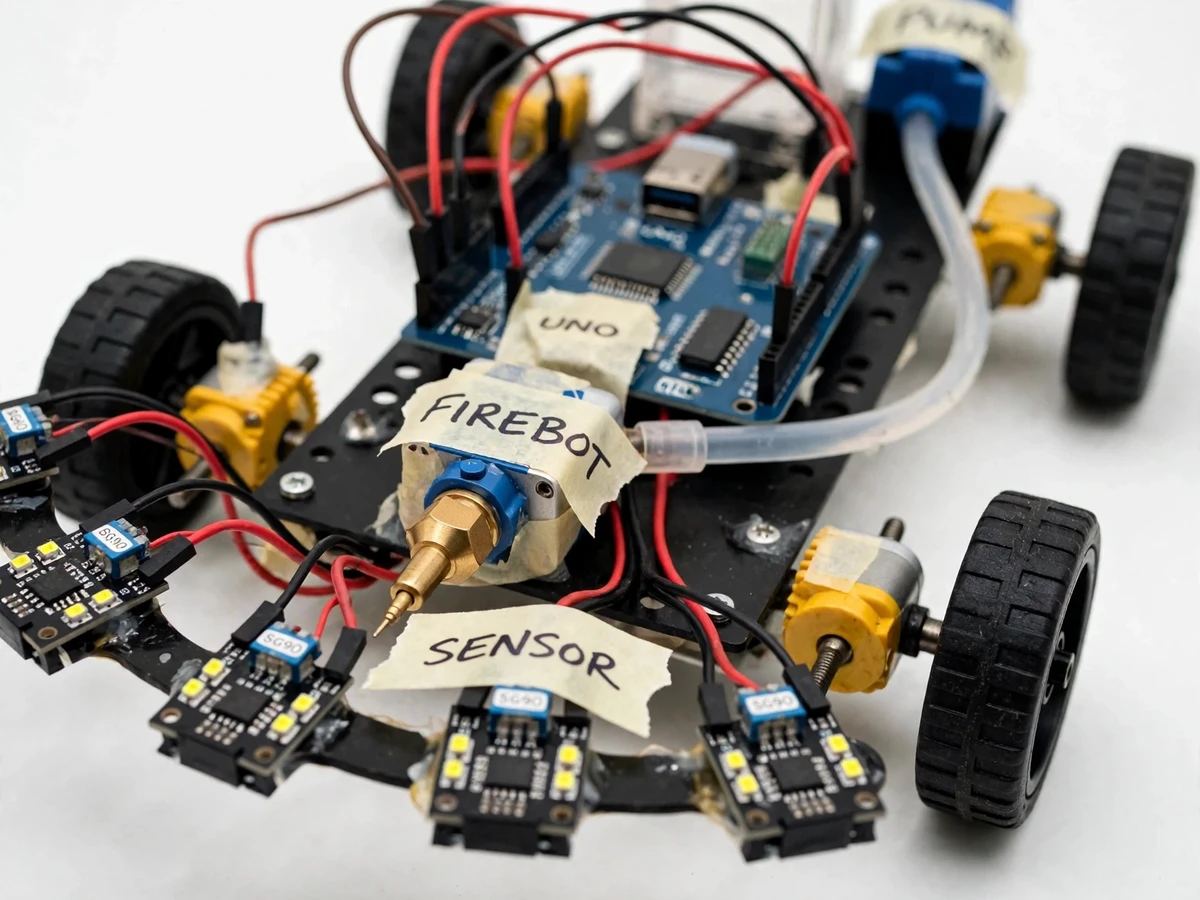
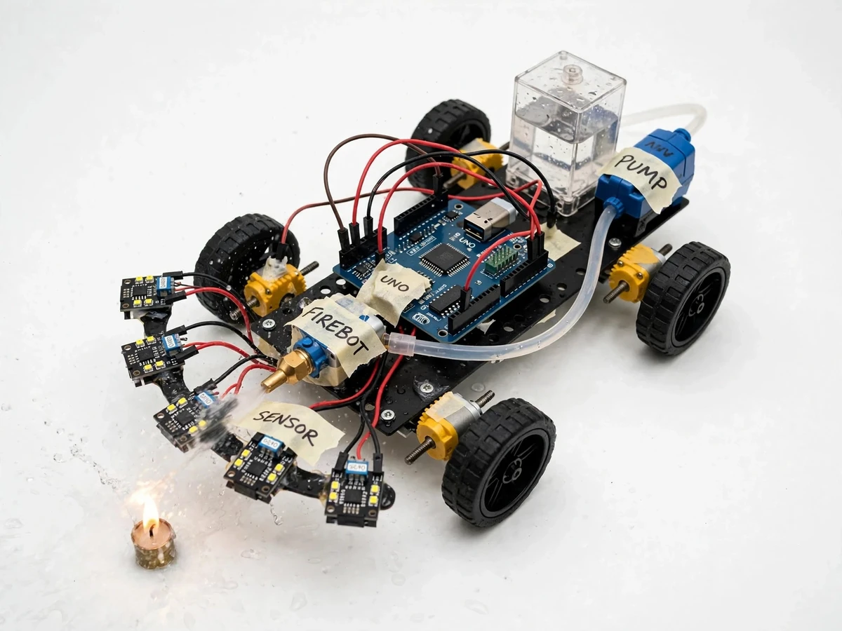
Responding to a small fire quickly is something a person standing nearby can do, but a wall-mounted detector can only sound an alarm — it cannot travel to the source. Students usually meet flame sensors and motor drivers as separate lab experiments, and rarely get to assemble them into one complete sense–decide–act machine. This project builds exactly that: a compact fire fighting robot that moves on its own, detects a flame with an array of IR flame sensors, drives toward it, and puts it out with a pump-driven water jet that a servo sweeps across the fire. Every part of the loop stays visible and explainable — sensing, threshold comparison, differential-drive steering and actuator control — which makes it a strong embedded-systems demonstration. It is strictly a lab-scale demonstration prototype, not a fire-safety device.
Five IR modules scan the forward arc for flame
Follow the working sequence
How it works
- The five flame sensors continuously monitor the forward arc for infrared emission in the 760–1100 nm band; each module compares its photodiode reading against a potentiometer-set threshold and raises a digital line when flame is present.
- The Arduino UNO polls the sensor lines and reads the analog values used for distance estimation, identifying the direction of the strongest flame signal.
- The L298N motor driver receives differential-drive commands: the robot turns toward the strong side and moves forward when the center sensors dominate, slowing as the signal intensifies.
- When the close-range condition is met, the drive motors stop and a 5 V relay switches the submersible pump on, spraying water from the onboard tank through the servo-mounted nozzle.
- The SG90 servo sweeps the nozzle across an adjustable arc, covering the flame front until every sensor reading falls back below threshold.
- The buzzer and red LED stay active through the whole engagement and switch off when the flame is declared out; the robot then resumes scanning for any remaining fire.
Tech stack:
- Arduino UNO (ATmega328P)
- Arduino IDE (C/C++)
- IR flame sensor modules (KY-026)
- L298N motor driver
- DC gear motors (4-wheel chassis)
- 5 V relay module
- 5 V submersible water pump
- SG90 micro servo
| Parameter | Value |
|---|---|
| Controller | Arduino UNO (ATmega328P, 16 MHz) |
| Flame sensors | 5 × IR modules (KY-026), 760–1100 nm (datasheet) |
| Sensor outputs | Digital (threshold-adjustable) + analog for distance estimation |
| Detection distance | Approximately 0.5–1 m (design target, angle- and flame-size-dependent) |
| Drive | 4 × DC gear motors with differential steering via L298N |
| Water system | 5 V submersible pump drawing from onboard tank, switched by relay |
| Pump flow | Approximately 1.2 L/min (typical component datasheet) |
| Nozzle | SG90 servo sweep, approximately 180° (design target) |
| Water tank | Approximately 0.5 L onboard container (design target) |
| Alarm | Buzzer + red LED active during detection |
| Power | 12 V battery pack (typical); logic on regulated 5 V |
Project features
- [Directional flame-sensor array] Five IR flame-sensor modules (left-outer, left, center, right, right-outer) cover the robot's forward arc, and the Arduino compares their readings to decide which direction the flame lies in. Each module's sensitivity is adjustable through its onboard potentiometer.
- [Flame-seeking drive] The firmware steers the 4-wheel differential drive toward the sensor reporting the strongest flame signal and slows down as the signal grows — a proportional approach, not random wandering.
- [Pump-driven water jet] A 5 V relay module switches the submersible mini water pump that draws from the onboard tank; the Arduino never drives the pump directly, so the logic stays protected from motor current.
- [Servo-swept nozzle] The water outlet rides on an SG90 servo that sweeps the jet side to side, spreading water across the flame front instead of hitting one spot.
- [Stop-and-spray logic] When the flame signal indicates close range, the robot halts, runs the pump, and resumes scanning only after the readings drop below threshold — simple, verifiable decision logic.
- [Audible and visual alarm] A buzzer and a red LED activate the moment any sensor crosses threshold, so the detection event is unmistakable during a demonstration.
- [Adjustable behavior] Flame threshold, stop distance and servo sweep angle are defined as firmware constants, so the build can be tuned to the size of the demonstration room.
- [Separated power wiring] Motors and pump run from the 12 V battery pack while the Arduino and sensors run on regulated 5 V, keeping noisy power wiring away from the logic.
What is included
- Assembled and tested fire fighting robot prototype
- Arduino firmware source code (commented, with tunable parameters)
- Wiring diagram and connection documentation
- Component list with specifications
- Project report PDF (background, design, methodology, results)
- PPT presentation for review/viva
- Viva Q&A preparation document
- Demonstration guidance (setup, safe flame source, tuning)
Limitations & prerequisites
- This is a lab-scale demonstration prototype, NOT a fire-safety device — it carries no certification, has not been tested against real fires, and must never be relied on for protecting life or property.
- Flame sensors respond to infrared sources in general — strong sunlight, halogen lamps and other hot IR emitters can cause false triggers.
- Detection distance (approximately 0.5–1 m, design target) depends on flame size, angle of incidence and ambient light; small or sheltered flames may not be detected reliably.
- The onboard tank carries approximately 0.5 L of water, so the robot can only handle a small demonstration flame.
- Demonstrations use a controlled flame source (for example a candle) under supervision — never operate the robot near anything flammable.
- Battery runtime varies with load; continuous driving plus pumping drains the pack faster than idle scanning, so keep a spare charged pack for the viva.
Frequently Asked Questions
Which controller and sensors does it use?
An Arduino UNO (ATmega328P) reads five IR flame-sensor modules of the KY-026 type. The sensors detect infrared emission in the 760–1100 nm band from flames; each module gives a digital output with a potentiometer-adjustable threshold, plus an analog reading the firmware uses for distance estimation. A L298N driver handles the four DC gear motors.
How far away can it detect a flame?
The design target is roughly 0.5–1 m, but real detection depends on flame size, angle of incidence and ambient light — a candle at half a meter is typical, while a large flame can register farther away and a sheltered one can be missed. The report presents distances measured on the build's own test bench, with no certified fire-response figure claimed.
Can this replace real firefighting equipment?
No — absolutely not. This is an academic demonstration of sensing, control and actuation with no certifications and no testing on real fires; its small tank and limited sensor range confine it to controlled lab demonstrations. Use it to learn embedded systems, never to protect any space.
What power supply does the robot need?
A 12 V battery pack (a rechargeable 12 V pack or 8 × AA cells, typical) drives the motors and pump, while the Arduino and sensors run on regulated 5 V; a 5 V relay module isolates the pump from the logic supply. Runtime varies with driving and pumping load, so keep a spare charged pack ready for the viva.
Can the project be customized?
Yes — realistic options include a Bluetooth manual-override control, an ESP32-CAM for a live video feed, extra sensors such as ultrasonic obstacle avoidance or a gas sensor for smoke, a larger tank and pump, or line-following for a guided demonstration course. Each addition is scoped separately against technical feasibility and timeline.
Is this project suitable for a final-year project?
Yes — for Electronics, E&TC, Electrical and Robotics programs. It demonstrates sensor interfacing, threshold and directional logic, motor drivers, relay control, servo actuation and complete system integration, and the report frames each of these topics for viva questions, so the student can demonstrate and explain every subsystem confidently. Suitable for B.E./B.Tech final-year projects in Electronics and Telecommunication (E&TC).
Components & software requirements
- Arduino UNO (ATmega328P)
- Arduino IDE (C/C++)
- IR flame sensor modules (KY-026)
- L298N motor driver
- DC gear motors (4-wheel chassis)
- 5 V relay module
- 5 V submersible water pump
- SG90 micro servo
Delivery information
Built-to-order project. Delivery timeline is shared after order confirmation based on current queue.
Support terms
Complete documentation, setup guide, and viva preparation included. Support for setup and explanation provided.
Download free synopsis (PDF)
Enter your name and email — the synopsis PDF downloads immediately. We may send occasional project updates; no spam, unsubscribe anytime.