
More project photos (3)
The problem
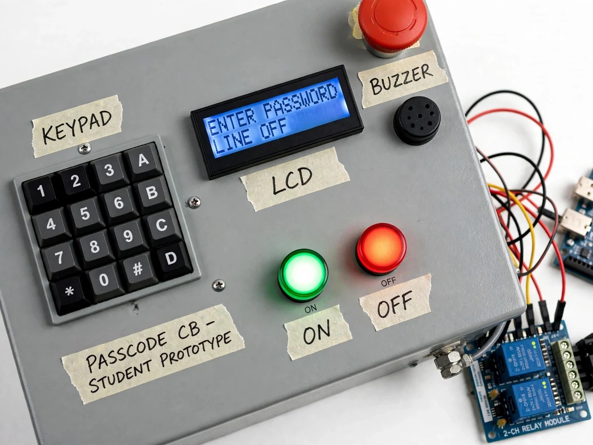
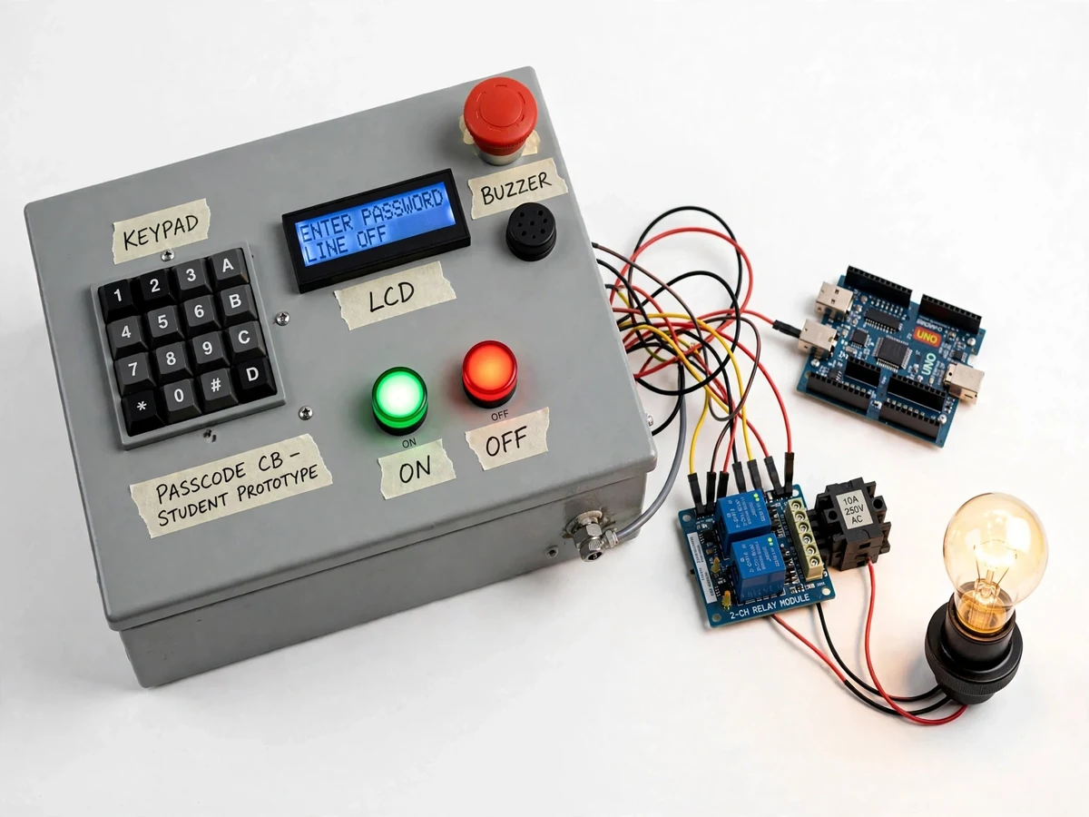
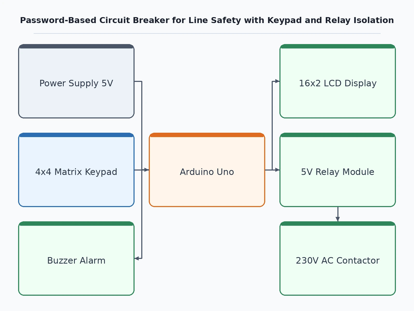
Line-maintenance electrocution is one of the oldest hazards in electrical work: a lineman is repairing a feeder while, somewhere else, a breaker is switched back on by someone who never knew work was in progress. Procedural safeguards like lockout tags exist, but they rely on everyone at the panel following the same process, and on many small panels and college-lab switchboards no physical lockout exists at all. This project replaces trust with a password. A circuit-breaker panel for a single-phase distribution line is built around an Arduino: the line can only be energized after a 4-digit crew password is entered on a 4x4 keypad. The microcontroller verifies the code, then drives a relay module and contactor to close the line; wrong attempts keep the line open, sound a buzzer, and are shown on a 16x2 LCD. The concept maps directly onto real lockout-tagout practice, is entirely buildable from common modules, and gives students a genuine electrical-safety project rather than another sensor demo.
Authorised crew entering the panel password.
Follow the working sequence
How it works
- At power-up the Arduino holds the relay driver OFF (line open), initializes the 16x2 LCD and loads the stored 4-digit code from EEPROM.
- The LCD prompts ENTER PASSWORD; each keypad press echoes as an asterisk so the code stays hidden from bystanders.
- The firmware compares the entered digits with the stored code. On a match it switches on the relay driver transistor, the relay module closes, and the contactor coil pulls in to complete the line — the LCD shows LINE ON and the green lamp lights.
- To switch the line OFF, the crew enters the password again, or anyone can press the red OFF pushbutton — the off path never needs the password, so de-energizing is always immediate.
- A wrong entry shows WRONG PASSWORD, increments a failure counter and sounds the buzzer; after 3 consecutive failures the buzzer stays on for about 10 seconds and, if the GSM module is fitted, an SMS alert goes out.
- The password is changed through a dedicated routine: the current code must be entered first, then the new 4-digit code is written to EEPROM and confirmed on the LCD.
Tech stack:
- Arduino Uno (ATmega328P)
- 4x4 membrane keypad
- 16x2 character LCD with I2C backpack
- 2-channel 5 V relay module
- AC contactor, 230 V AC coil class
- Piezo buzzer, pushbuttons and indicator lamps
- Embedded C++ in the Arduino IDE
- SIM800L GSM module (optional add-on)
| Parameter | Value |
|---|---|
| Controller | Arduino Uno (ATmega328P, 16 MHz) |
| Password length | 4 digits, user-changeable |
| Password storage | EEPROM (retained across power cycles) |
| Keypad | 4x4 membrane, 16 keys |
| Display | 16x2 character LCD with I2C backpack |
| Relay module | 2-channel, 5 V DC coil, 10 A / 250 V AC contact rating (datasheet) |
| Contactor stage | 230 V AC coil class; power-contact rating per chosen contactor datasheet |
| Wrong-attempt lockout | 3 attempts, buzzer approximately 10 s (design target) |
| Relay response | Pull-in within approximately 50 ms of a valid entry (expected) |
| Demo load | 230 V bulb in a holder (demonstration only) |
| Control supply | 5 V DC regulated for the logic section |
Project features
- [Password-locked line switching] The line energizes only after the correct 4-digit crew code is entered on the 4x4 keypad; every keypress echoes as an asterisk on the LCD so the code cannot be read over a shoulder.
- [Relay and contactor isolation] The Arduino drives a 2-channel 5 V relay module, which switches a 230 V AC contactor coil — the line itself is handled by the contactor's power contacts, never by the microcontroller board.
- [Wrong-password buzzer alarm] A wrong entry flashes a warning on the LCD and sounds the buzzer; after 3 consecutive failures the alarm stays on for about 10 seconds as a tamper deterrent.
- [Live status on 16x2 LCD] The display walks the user through every state: ENTER PASSWORD, LINE ON, LINE OFF and WRONG PASSWORD, so the panel needs no guesswork in the field.
- [Changeable password in EEPROM] An authorized routine (old code first) lets the crew set a new 4-digit code, which is stored in EEPROM and survives power cycles.
- [Fail-safe line-off path] A red OFF pushbutton opens the line immediately with no password required, so anyone can de-energize in an emergency while only the crew can re-energize.
- [Optional SMS tamper alert] With the optional SIM800L GSM module fitted, repeated wrong-password attempts trigger an SMS alert to the supervisor's phone.
What is included
- Working password-protected circuit-breaker panel prototype
- Arduino firmware source (keypad scan, LCD menus, relay control, EEPROM password storage, buzzer and alert logic)
- Circuit diagram and point-to-point wiring diagram
- Component list with datasheet references for the relay and contactor
- Project report PDF (background, lockout-tagout concept, design, wiring, testing)
- PPT presentation for final review
- Viva Q&A preparation document (relays vs contactors, EEPROM, debouncing, safety practice)
Limitations & prerequisites
- The password is stored in EEPROM as plain digits with no encryption — it stops casual misuse, not a determined attacker with physical access to the board.
- The shipped relay module is rated 10 A / 250 V AC per its datasheet; switching a real distribution feeder needs a contactor sized for that feeder, quoted separately.
- There is no remote SCADA, app or wireless control in the base build — all switching happens at the panel keypad.
- The prototype demonstrates on a lamp load; any mains wiring must be done or supervised by a qualified electrician.
- SMS alerts need the optional SIM800L module plus an active SIM with balance — not part of the base build.
- A forgotten password needs the physical master-reset routine; if the crew loses both the code and the reset procedure, the panel must be opened.
Frequently Asked Questions
How does a password actually protect the lineman?
The contactor that closes the line is driven only by the microcontroller, and the firmware closes it only after the crew's code is entered. A person who walks up to the panel and does not know the code physically cannot re-energize the line — the interlock is in the circuit, not in a procedure people may forget.
Can the crew change the password?
Yes. A dedicated change routine asks for the current code first, then accepts and stores a new 4-digit code in EEPROM. The new code survives power cuts because EEPROM is non-volatile.
What happens on repeated wrong entries?
Each wrong entry shows WRONG PASSWORD and sounds the buzzer briefly. After 3 consecutive failures the buzzer stays on for about 10 seconds, and with the optional GSM module fitted an SMS alert goes to the supervisor's number.
What real line voltage can this switch?
The base prototype switches a demonstration lamp load through the relay module (10 A / 250 V AC contact rating per its datasheet). For a real feeder, the design includes a contactor stage whose contact rating must match the feeder — that sizing is part of the build quotation.
Does it survive a power cut?
The password is kept in EEPROM, so it is retained without power. The logic section needs its 5 V supply to operate the keypad and relay, which a small UPS or battery pack can provide during outages.
Is this project suitable for a final-year project?
Yes — for Electrical engineering programs. It combines power switching (relays, contactors), embedded control, human-machine interface design and a genuine safety application with clear lockout-tagout relevance.
Components & software requirements
- Arduino Uno (ATmega328P)
- 4x4 membrane keypad
- 16x2 character LCD with I2C backpack
- 2-channel 5 V relay module
- AC contactor, 230 V AC coil class
- Piezo buzzer, pushbuttons and indicator lamps
- Embedded C++ in the Arduino IDE
- SIM800L GSM module (optional add-on)
Delivery information
Built-to-order project. Delivery timeline is shared after order confirmation based on current queue.
Support terms
Complete documentation, setup guide, and viva preparation included. Support for setup and explanation provided.
Download free synopsis (PDF)
Enter your name and WhatsApp number — the synopsis PDF downloads immediately. We may send occasional project updates on WhatsApp; no spam.