
More project photos (2)
The problem
A passive harmonic filter for single-phase loads is a shunt panel of series inductor-capacitor branches connected across the supply feeding a nonlinear load. What does a passive LC trap filter do for a single-phase load? It gives each targeted harmonic current an easy path to circulate through a tuned branch instead of flowing back into the supply, so the current drawn from the 230 V, 50 Hz source contains less of the 3rd and 5th harmonic content produced by a rectifier-type load. Each trap branch is designed so that its series impedance is at a minimum near its tuned frequency, which is why the 150 Hz branch attracts mainly 3rd harmonic current and the 250 Hz branch attracts mainly 5th harmonic current, while both branches present a much higher impedance at the 50 Hz fundamental.
| Filter or tool | What it does | What it does not do |
|---|---|---|
| This passive LC trap filter | Diverts 3rd and 5th harmonic currents through tuned shunt branches on a single-phase supply | It does not cancel harmonics it was not tuned for, and it does not regulate voltage |
| Active harmonic filter | Measures the distorted current and injects a cancelling current using power electronics | It is not a passive circuit, and it needs sensing, control and a switching converter |
| Capacitor-bank power-factor correction | Supplies reactive power with shunt capacitors to improve displacement power factor | It does not trap specific harmonics, and an untuned bank can resonate with supply inductance |
| Power-quality analyzer | Records and analyses voltage and current waveforms already present on a supply | It does not remove harmonics; it measures them so a filter can be designed or checked |
230 V supply feeds the load.
Follow the working sequence
How it works
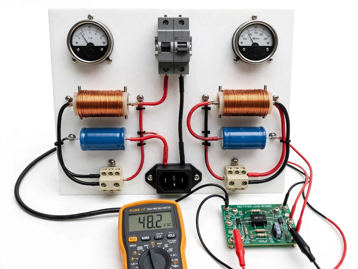
The filter works because a series inductor-capacitor branch has its lowest impedance at its resonant frequency, set by the component values through f = 1/(2π√LC). A rectifier-type load draws a pulsed current containing harmonic components at 150 Hz, 250 Hz and higher multiples of the 50 Hz fundamental, and those harmonic currents would otherwise flow back through the supply. Each trap branch is connected in parallel with the load, so it offers those harmonic currents an alternative path: at its tuned frequency the branch impedance falls to little more than its winding resistance, while at 50 Hz the same branch presents a much higher impedance and draws only a small fundamental current. The 150 Hz branch therefore diverts mainly 3rd harmonic current and the 250 Hz branch diverts mainly 5th harmonic current, leaving less of those two harmonics in the supply conductors, as panel meters and a current probe show.
- The nonlinear load draws a pulsed current from the 230 V, 50 Hz supply, and the supply current is recorded with both trap branches bypassed as the unfiltered reference.
- The 150 Hz trap branch is switched in, and the supply current and the branch current are recorded so the 3rd harmonic diversion can be compared with the reference.
- The 250 Hz trap branch is switched in alongside the first branch, and the same readings are repeated to show the combined effect on the supply waveform.
- Each branch is then switched out in turn, so the contribution of each trap can be separated in the lab record instead of being merged into one reading.
- An oscilloscope or harmonic measurement on the supply current shows the change in the 150 Hz and 250 Hz content between the bypassed and filtered cases.
- The branch inductor and capacitor values are checked against the tuning formula, and any difference between the design-target frequency and the measured resonance is noted as detuning in the report.
Builder note from the actual build: tune each branch with the load disconnected and verify its resonance with a signal source and a meter before connecting the panel to mains, because a branch tuned on paper can shift once it is wired. Keep trap-branch wiring short, since stray inductance in long leads adds to the branch inductance and moves the tuned frequency away from its design target. A trap is a frequency-selective shunt path, not a general clean-up device: it diverts the harmonics it is tuned for and leaves the rest of the spectrum largely unchanged.
Tech stack:
- Series LC trap branch for harmonic diversion
- Air-core inductor winding for trap branches
- AC film capacitor for trap branches
- MCB protection for panel input
- Analog panel ammeter and voltmeter
- Rectifier-type nonlinear test load
- Terminal blocks and selector switches
- Oscilloscope current measurement for verification
| Parameter | Value |
|---|---|
| Input supply | 230 V AC at 50 Hz (design input) |
| Load type | Single-phase rectifier-type nonlinear load (design target) |
| 3rd harmonic trap frequency | 150 Hz (design target) |
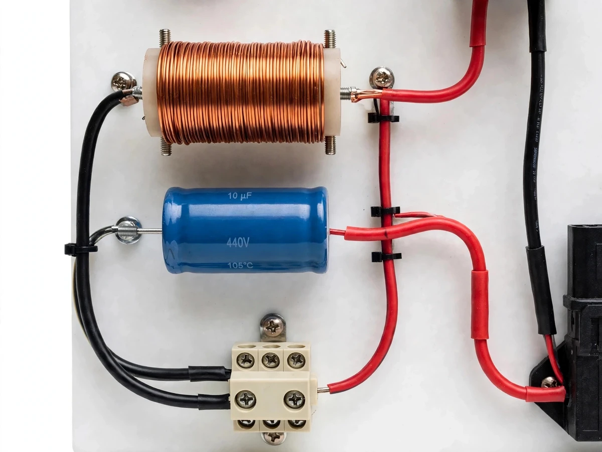
| 3rd harmonic branch | 10 µF capacitor (design target) with 113 mH inductor (design target, from f = 1/(2π√LC)) |
| 5th harmonic trap frequency | 250 Hz (design target) |
| 5th harmonic branch | 6.8 µF capacitor (design target) with 60 mH inductor (design target, from f = 1/(2π√LC)) |
| Tuning formula | f = 1/(2π√LC), applied per branch (design method) |
| Capacitor voltage rating | 440 V AC (component rating) |
| Panel protection | MCB rated 6 A (component rating) |
| Measurement | Panel ammeter 0–5 A (component rating) and voltmeter 0–300 V (component rating) |
| Test load rating | Rectifier load up to 500 W (design target) |
| Construction | Single labelled bench panel with shunt trap branches and selector switches |
Project features
A passive harmonic filter earns its place in an electrical lab through four capabilities: two shunt trap branches tuned to the harmonics a rectifier load produces, a tuning method students can check with a formula before any mains connection, panel meters showing supply current before and after filtering, and a protected panel layout with short, labelled trap connections. The 150 Hz branch targets the 3rd harmonic and the 250 Hz branch targets the 5th harmonic, so a lab session can switch branches in and out and compare the supply waveform for each case. With no control software or switching converter to tune, the experiment stays focused on resonance, impedance and waveform measurement. Each branch can be isolated for its own resonance check, and the panel wiring makes the shunt connection visible: the trap sits across the supply, in parallel with the load, rather than in series with it.
- [Two tuned trap branches] One branch tuned near 150 Hz (design target) for the 3rd harmonic and one near 250 Hz (design target) for the 5th harmonic, each switchable independently so the effect of each branch can be measured on its own.
- [Formula-checked tuning] Each branch follows f = 1/(2π√LC), with the inductor and capacitor values chosen as design targets from that formula, so students can repeat the tuning arithmetic and check it against a resonance measurement.
- [Visible shunt connection] The trap branches connect across the supply in parallel with the load, with labelled terminals and short branch wiring, so the shunt filtering concept is visible on the panel instead of hidden inside a box.
- [Before-and-after current measurement] Panel ammeter and voltmeter terminals plus a meter connection point let students record the supply current with the filter bypassed and with each branch connected, using the same load and the same instruments.
- [Rectifier-type test load] A rectifier load board represents the nonlinear load that produces the harmonics, so the filter is tested against a real distorted current rather than a signal-generator imitation alone.
- [MCB protection and isolated terminals] An MCB guards the panel input and the load and filter connections use shrouded terminals, so a wiring fault trips protection and live parts are not left exposed on the bench.
- [Lab-ready labelled panel] Inductors, capacitors, switches, meters and terminals are mounted on one labelled bench panel with documented wiring, so the unit can be set up and demonstrated without loose bench wiring.
Implemented in the base build: the two trap branches tuned near 150 Hz and 250 Hz (design targets), branch selector switches, panel meters, MCB protection, and the rectifier-type test load connection. Optional on request: a third branch tuned near 350 Hz (design target) for the 7th harmonic, or a detuned reactor option for a capacitor-bank study. Future scope only, not in the base build: automatic harmonic spectrum logging to a computer.
What is included
- Assembled passive harmonic filter panel with two LC trap branches, selector switches, meters and MCB protection
- Rectifier-type test load board for the output terminals
- Tuning calculations for both branches showing the f = 1/(2π√LC) arithmetic
- Circuit and wiring documentation for the panel
- Component list with part ratings
- Lab experiment guide covering unfiltered reference readings, single-branch readings and combined-branch readings
- Project report PDF (background, tuning theory, methodology, observations format)
- PPT presentation for final review
- Viva Q&A preparation document covering resonance, trap impedance, harmonic orders and safety
To get a quotation, send your load type and the harmonic branches you need on WhatsApp, and Projectech will reply with a quotation stating the price and the delivery timeline for your build.
Limitations & prerequisites
- This filter is tuned to the 3rd and 5th harmonics only: harmonics at other orders, such as the 7th at 350 Hz (design target), pass largely unaffected unless a branch is added for them.
- Detuning shifts performance: if the load, the supply impedance or the branch wiring changes, the actual resonance moves away from the 150 Hz and 250 Hz design targets and diversion weakens.
- No active compensation is included: the filter cannot adapt to a changing load spectrum, cancel harmonics dynamically, or regulate voltage.
- No measured THD reduction is claimed: the delivered unit's harmonic readings must be recorded with lab instruments during commissioning, and the report presents design targets alongside those measured readings.
- This is a teaching and laboratory filter, not a certified power-quality device: it does not certify an installation and no compliance result is claimed for it.
- Mains-voltage work requires instructor supervision: the panel must be used under instructor supervision with standard electrical-lab safety practice.
Frequently Asked Questions
How does an LC trap branch remove a harmonic?
A series inductor-capacitor branch has its lowest impedance at its resonant frequency, which is set by its component values through the formula f = 1/(2π√LC). At that frequency the branch offers harmonic current an easy shunt path in parallel with the load, so that harmonic circulates through the trap instead of flowing back into the supply conductors. At the 50 Hz fundamental the same branch has a much higher impedance, so it draws only a small fundamental current and leaves the useful power flow largely alone.
Why are the branches tuned to 150 Hz and 250 Hz?
A rectifier-type load on a 50 Hz supply produces harmonic currents at multiples of the fundamental, and the 3rd harmonic falls at 150 Hz while the 5th harmonic falls at 250 Hz. Those two orders usually dominate the distorted current of a single-phase rectifier load, so tuning one branch to each gives a lab experiment two clear, separable cases to measure. Other orders remain in the current, which is why the filter is described as targeting two harmonics rather than cleaning the whole waveform.
How are the inductor and capacitor values chosen?
The capacitance is chosen first and the inductance is then calculated from the tuning formula, giving a 113 mH design target with a 10 µF capacitor for the 150 Hz branch and a 60 mH design target with a 6.8 µF capacitor for the 250 Hz branch. These are design targets from the formula, not measured values, verified with a signal source before any mains connection. If the measured resonance differs, the difference is recorded as detuning and the branch is adjusted or documented as built.
Is this filter the same as power-factor correction?
No, because a capacitor bank for power-factor correction supplies reactive power to improve displacement power factor, while a trap filter is tuned to divert specific harmonic currents through a low-impedance shunt path. A plain capacitor bank is not tuned to a harmonic frequency and can even resonate with supply inductance, which is a different problem from the one a trap solves. The two can appear on the same panel in other designs, but in this build the branches are traps first, and any fundamental reactive current they draw is a side effect to note, not the purpose.
Can this filter be used on a real installation?
No, not as a certified device, because this build is a teaching and laboratory filter sized for a bench test load and supervised lab experiments rather than for a building or factory supply. A real installation needs a site survey, a measured harmonic spectrum, protection coordination and compliance checks that are outside the scope of this project. Students can still learn the tuning and measurement method here and then explain, in a viva, what additional work a real installation would require before any filter is connected to it.
Is this project suitable for a final-year project?
Yes, for Electrical and Electronics programmes, because it combines power systems theory with resonance, inductor and capacitor selection, and waveform measurement in one working bench build. A student can derive the tuning from first principles, demonstrate each branch switching in and out, and present before-and-after supply current readings. The report and experiment guide give the documentation a review panel expects alongside the hardware.
Components & software requirements
- Series LC trap branch for harmonic diversion
- Air-core inductor winding for trap branches
- AC film capacitor for trap branches
- MCB protection for panel input
- Analog panel ammeter and voltmeter
- Rectifier-type nonlinear test load
- Terminal blocks and selector switches
- Oscilloscope current measurement for verification
Delivery information
Built-to-order project. Delivery timeline is shared after order confirmation based on current queue.
Support terms
Complete documentation, setup guide, and viva preparation included. Support for setup and explanation provided.
Download free synopsis (PDF)
Enter your name and WhatsApp number — the synopsis PDF downloads immediately. We may send occasional project updates on WhatsApp; no spam.