
More project photos (3)
The problem
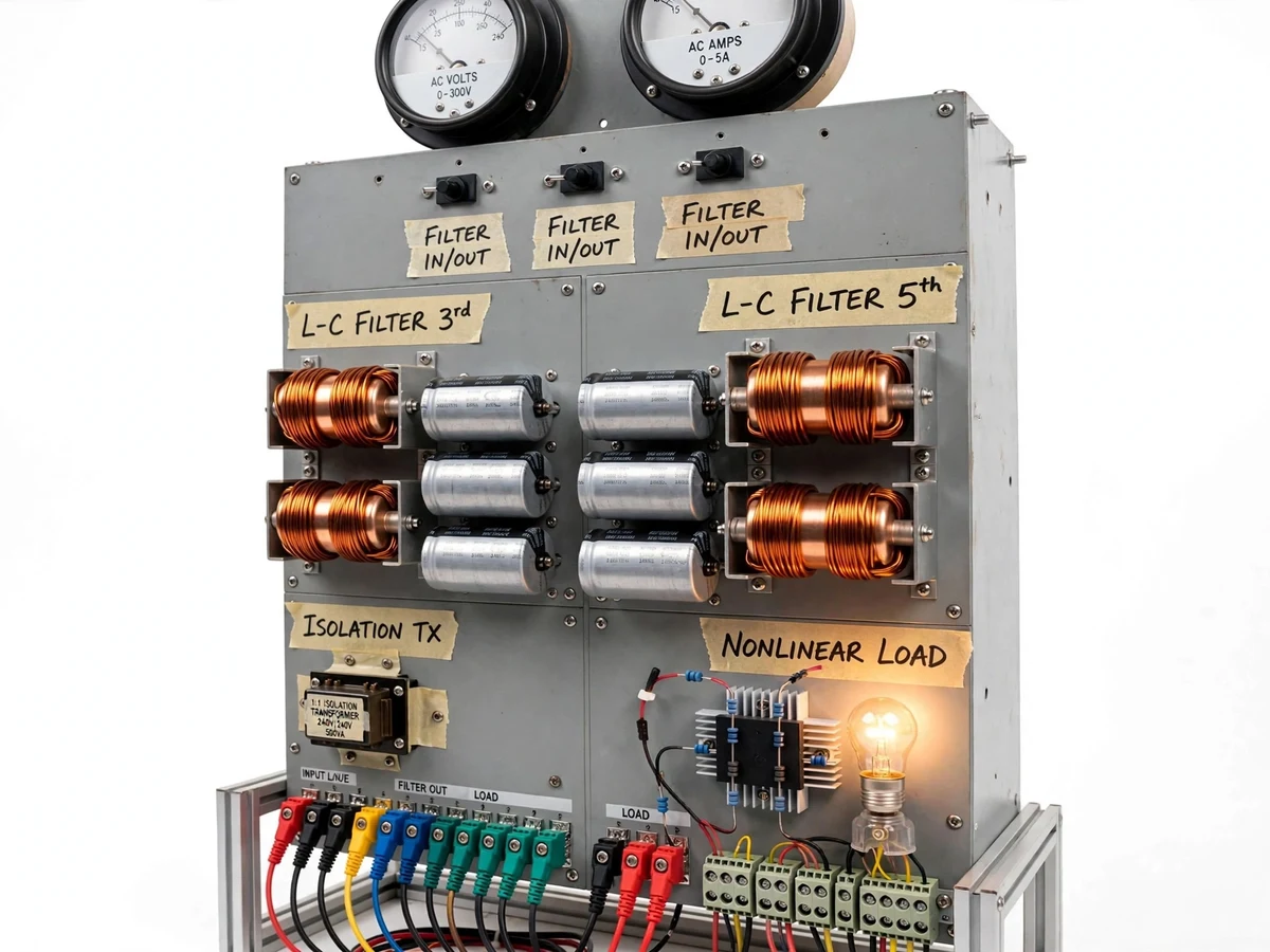
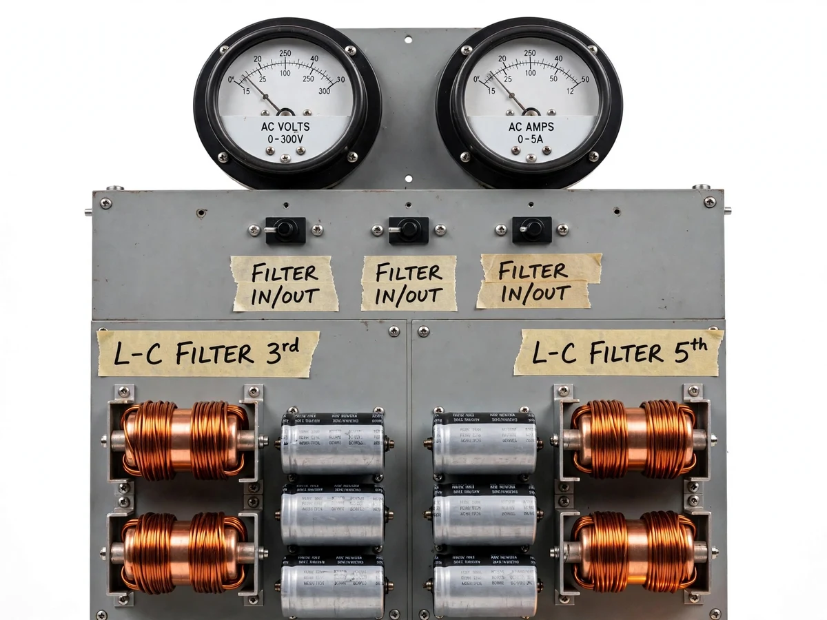
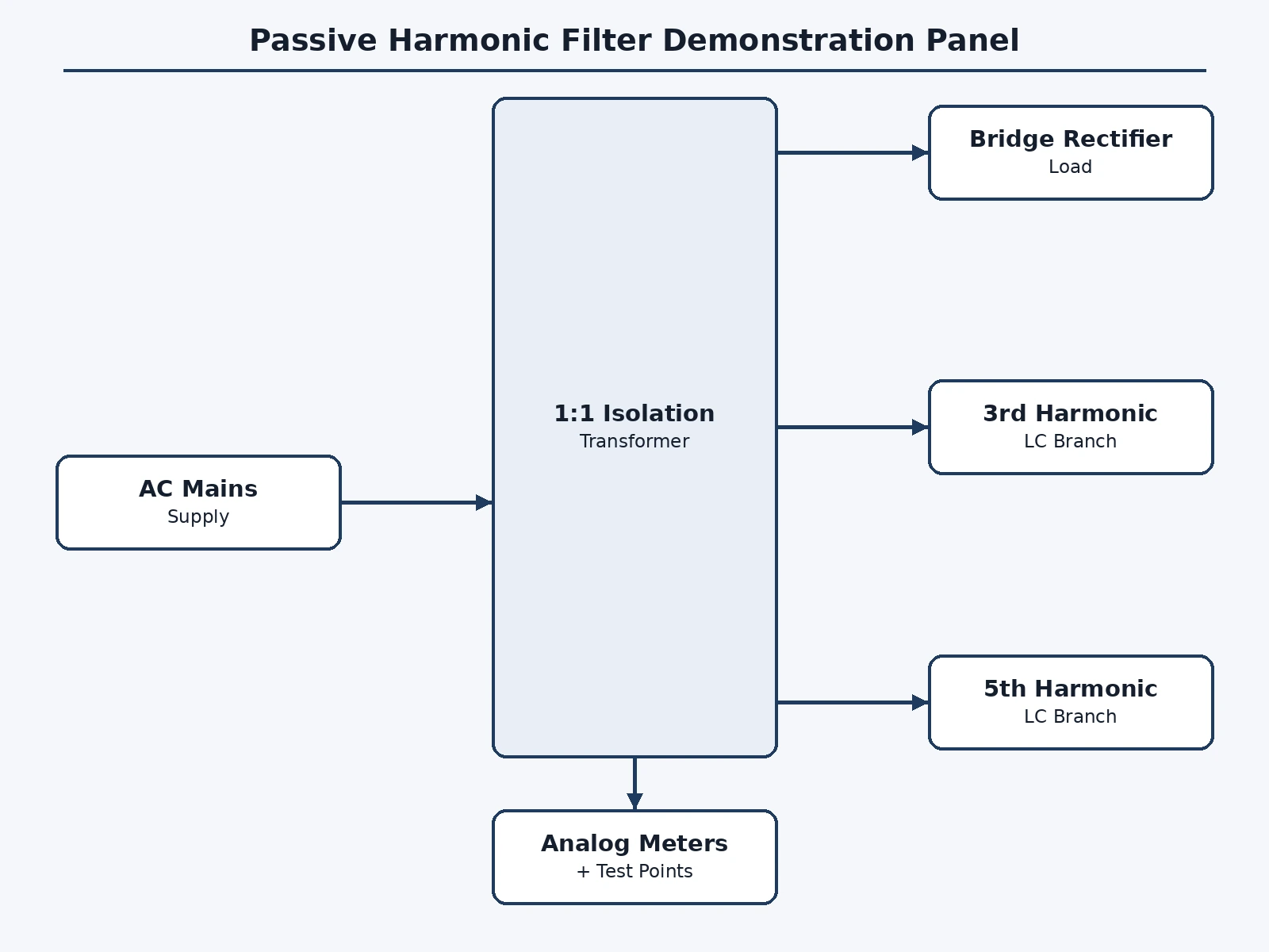
Harmonics are easy to derive on paper and hard to believe until seen: a rectifier load's current waveform looks nothing like a sine wave, and the textbook fix — a series LC branch tuned to resonate at a harmonic frequency — feels abstract until a meter needle moves. This demonstration panel closes that gap. A 1:1 isolation transformer feeds a bridge-rectifier-plus-capacitor nonlinear load with a lamp, producing the classic distorted current. Two LC shunt filter branches, tuned to the 3rd (150 Hz) and 5th (250 Hz) harmonics, sit behind FILTER IN/OUT toggle switches; engaging each branch while watching the analog AC meters and the oscilloscope test points shows the harmonic current being diverted and the supply current visibly cleaning up. Component values are derived from the tuning relation f = 1/(2π√(LC)) with standard-value selection documented in the report. The panel is deliberately honest: no THD numbers are printed in this listing because THD is what the buyer measures, live, with their own instruments during the demonstration.
230 V AC fed through the 1:1 isolation transformer and panel fuses.
Follow the working sequence
How it works
- The panel is powered through the 1:1 isolation transformer and fuses; the nonlinear load (bridge rectifier, capacitor, lamp) is switched on first.
- With both filter branches OUT, the supply current waveform at the test points shows the distorted, peaked shape of rectifier loading; the meters read the unfiltered state.
- The 3rd-harmonic branch is switched IN: its series LC offers minimum impedance near 150 Hz, sinking that harmonic current away from the supply.
- The 5th-harmonic branch is switched IN the same way, targeting the 250 Hz component; each engagement is visible on the meters and scope.
- The student captures "before" and "after" waveforms and computes THD improvement with their own scope or power analyzer — the measurement is the demo, not a printed claim.
- Switching a branch back OUT restores the distorted state, proving the effect is the filter's and repeatable on demand.
- The report's calculation annex shows the L-C tuning derivation and the effect of standard-value rounding on the resonant frequency.
Tech stack:
- 1:1 isolation transformer (100 VA class, design target)
- Bridge rectifier + DC-link capacitor nonlinear load
- Air-core inductors + AC-rated capacitors (LC branches)
- Analog AC voltmeter and ammeter (panel meters)
- Toggle switches (filter IN/OUT)
- Banana-jack test points + terminal blocks
- Panel fuses and wiring
- Oscilloscope / power analyzer (buyer's instrument for measurement)
| Parameter | Value |
|---|---|
| Supply | 230 V AC via 1:1 isolation transformer (100 VA class, design target) |
| Nonlinear load | Bridge rectifier + capacitor + lamp (design target) |
| Filter branches | 2 switched LC shunts, 3rd and 5th harmonic |
| Tuning | f = 1/(2π√(LC)); 150 Hz and 250 Hz targets (design targets) |
| Metering | Analog AC volts + AC amps, panel-mounted |
| Test points | Banana jacks for scope current/voltage capture |
| Protection | Panel fuses + isolation transformer |
| THD figures | Measured by buyer during demo — no values claimed in this listing |
| Panel | Bench-top metal panel with labeled sections |
Project features
- [Nonlinear load stage] Bridge rectifier with DC-link capacitor and lamp load draws the classic peaked, harmonic-rich current for the "before" picture.
- [3rd-harmonic LC branch] Series inductor-capacitor shunt tuned near 150 Hz, switchable in and out independently.
- [5th-harmonic LC branch] Series inductor-capacitor shunt tuned near 250 Hz, switchable in and out independently.
- [Analog metering] Panel AC voltmeter and ammeter show supply quantities changing as each filter engages.
- [Oscilloscope test points] Banana-jack points for current and voltage waveforms so the before/after shapes are captured on the buyer's scope.
- [Isolation + fusing] A 1:1 isolation transformer and panel fuses keep the classroom demo at safe, bounded energy.
- [Documented tuning maths] L and C selection from f = 1/(2π√(LC)) with standard-value rounding and the resulting detuning explained, not hidden.
- [Step-by-step demo procedure] A scripted sequence — load only, 3rd in, 5th in, both in — the student runs for examiners.
What is included
- Fully wired demonstration panel: transformer, load stage, two LC filter branches, meters, switches, test points, fusing
- L-C tuning calculation sheet with standard-value selection
- Scripted demonstration procedure for examiners
- Wiring diagram and connection table
- Project report PDF (background, harmonics theory, filter design, methodology, demo results template, limitations)
- PPT presentation for final review
- Viva Q&A preparation document (harmonic sources, series vs shunt filters, resonance, tuning, detuning)
Limitations & prerequisites
- No THD or harmonic-current figures are claimed in this listing — the panel is the demonstration platform, and improvement is measured live by the buyer with a scope or analyzer.
- The filters are tuned to the demo load's dominant harmonics; a different load would need retuned branches (the calculation sheet shows how).
- Passive filters can resonate with supply impedance at non-tuned frequencies; the report discusses this risk and why the demo stays at low power.
- Single-phase demonstration only; three-phase harmonic behaviour is discussed in theory, not demonstrated.
- The buyer needs access to an oscilloscope or power analyzer to capture the before/after waveforms — the panel provides the test points, not the instrument.
Frequently Asked Questions
What will examiners actually see?
The distorted supply-current waveform of the rectifier load on the scope, then each filter branch switched in with the waveform visibly cleaning up and the panel meters responding. The student then computes the THD improvement from their own captured waveforms.
Why no THD numbers in the listing?
Because THD depends on the exact load, component tolerances and the measuring instrument — printing a number would be inventing a test result. The honest deliverable is the platform plus the procedure; the measurement happens live.
How are the L and C values chosen?
From the series-resonance relation f = 1/(2π√(LC)) at 150 Hz and 250 Hz, then rounded to standard component values. The calculation sheet shows the rounding and the resulting detuning, which itself is a good viva discussion.
Is it safe for a classroom demo?
Yes by design: a 1:1 isolation transformer bounds the energy, panel fuses protect each section, and all live parts are behind the panel face with only banana-jack test points exposed. Standard lab precautions still apply.
Can it filter a real building's harmonics?
No — it is a low-power teaching demonstrator, not a power-factor-correction installation. Real installations need detuned banks, resonance studies and utility coordination, covered in the report's future scope.
Is this project suitable for a final-year project?
Yes — for Electrical programs. It turns power-quality theory into a hands-on demo: harmonic generation, LC tuning, resonance awareness and live measurement. Suitable for B.E./B.Tech final-year projects in Electrical.
Components & software requirements
- 1:1 isolation transformer (100 VA class, design target)
- Bridge rectifier + DC-link capacitor nonlinear load
- Air-core inductors + AC-rated capacitors (LC branches)
- Analog AC voltmeter and ammeter (panel meters)
- Toggle switches (filter IN/OUT)
- Banana-jack test points + terminal blocks
- Panel fuses and wiring
- Oscilloscope / power analyzer (buyer's instrument for measurement)
Delivery information
Built-to-order project. Delivery timeline is shared after order confirmation based on current queue.
Support terms
Complete documentation, setup guide, and viva preparation included. Support for setup and explanation provided.
Download free synopsis (PDF)
Enter your name and WhatsApp number — the synopsis PDF downloads immediately. We may send occasional project updates on WhatsApp; no spam.