
More project photos (3)
The problem
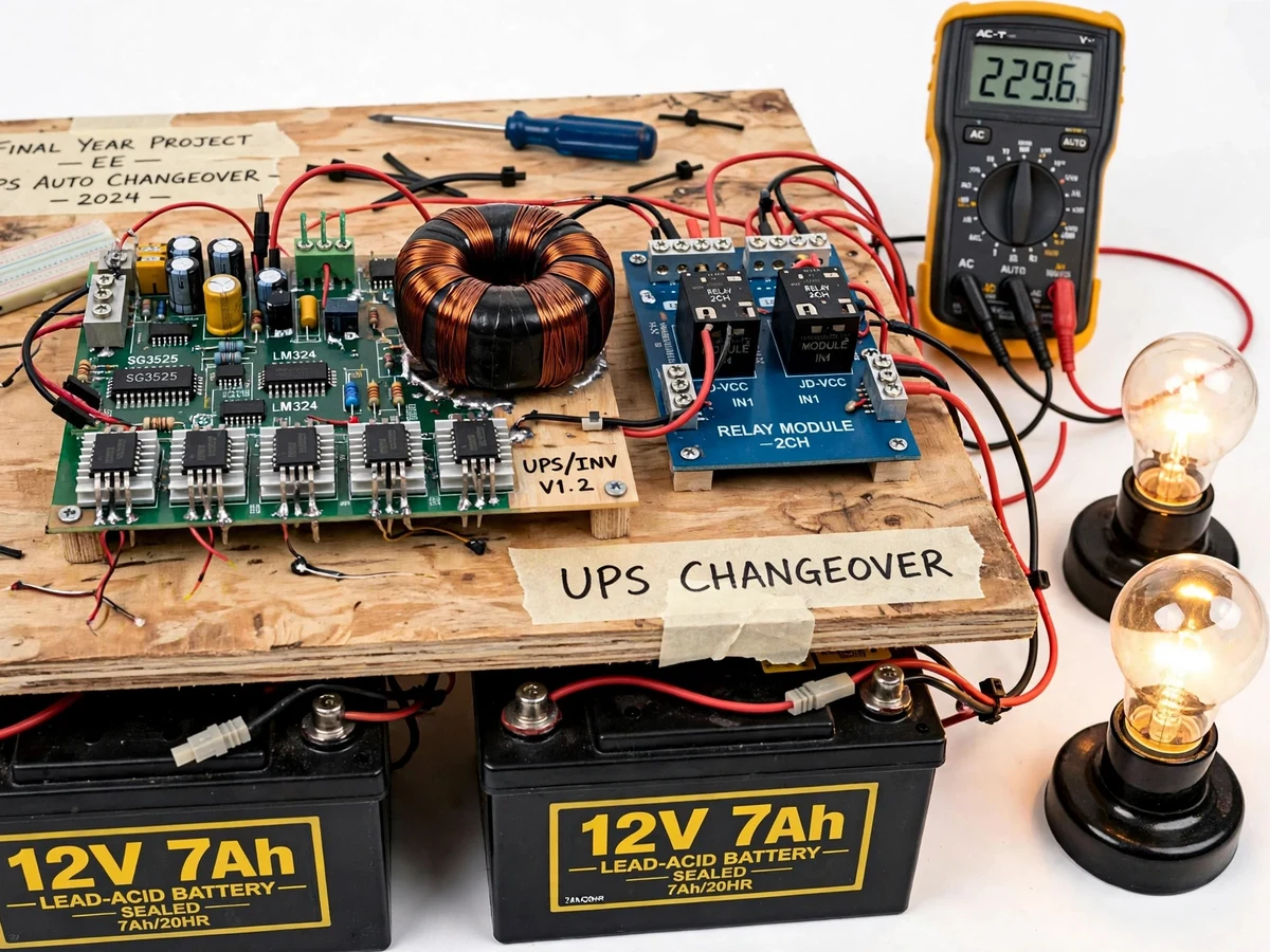
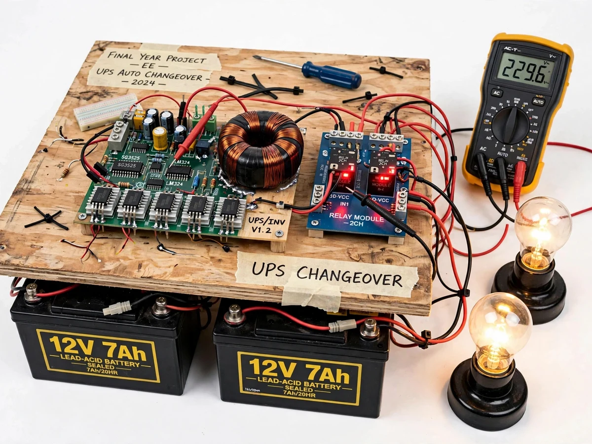
Most electrical students study uninterruptible power supplies only as block diagrams: battery, inverter, charger, changeover switch. The part they never get to see working is the actual mains-fail event — the sensing, the relay throw, the load surviving the transition. This project turns that event into a demonstrable bench rig. A hand-built SG3525 PWM inverter board drives AC lamp loads through a toroidal step-up transformer, backed by two 12 V 7 Ah batteries. A 2-channel relay changeover module, driven by a mains-sensing comparator stage, moves the loads between mains and inverter automatically when the mains is disconnected and restored. A digital multimeter on the board monitors output voltage throughout, so the student can verify the transition live.
Two 12 V 7 Ah sealed lead-acid batteries that feed the inverter board.
Follow the working sequence
How it works
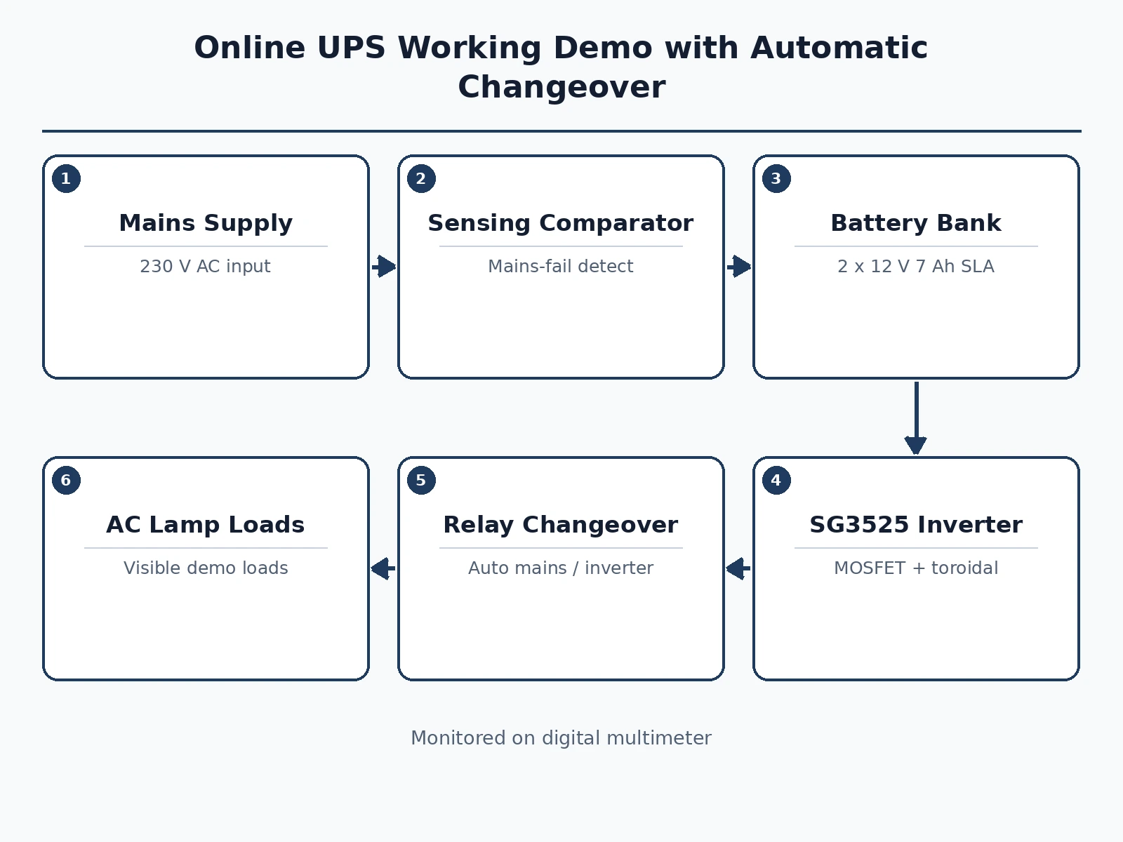
- Two 12 V 7 Ah batteries feed the SG3525 inverter board, which generates a PWM drive for the MOSFET stage and the toroidal transformer.
- The transformer steps the inverter output up to mains-level AC (design target approximately 230 V), feeding one side of the 2-channel relay changeover module.
- A mains-sensing comparator stage watches the incoming mains supply; while mains is healthy, the relays connect the lamp loads to mains.
- When mains fails (demonstrated by unplugging the mains lead), the sensing stage drops out and the relays transfer the loads to the inverter output automatically.
- On mains restoration, the relays transfer the loads back to mains; the inverter idles back on battery standby.
- The digital multimeter stays connected to the changeover output throughout, so output voltage is readable in every state.
Tech stack:
- SG3525 PWM inverter board with LM324 feedback
- Toroidal step-up transformer
- 12 V 7 Ah sealed lead-acid batteries (x2)
- 2-channel relay changeover module
- Mains-sensing comparator stage
- Digital multimeter for output monitoring
- AC lamp test loads
- Wooden base board with labeled wiring
| Parameter | Value |
|---|---|
| Inverter control | SG3525 PWM controller (datasheet part) |
| Output voltage | Approximately 230 V AC (design target, buyer-verified during calibration) |
| Output frequency | Approximately 50 Hz (design target, set by PWM timing network) |
| Battery bank | 2 x 12 V, 7 Ah sealed lead-acid (datasheet ratings) |
| Changeover | 2-channel relay module, mains-sense driven |
| Test load | 2 x AC lamps (design target approximately 40 W combined) |
| Backup time | Varies with load; measured by the buyer during the test procedure |
| Monitoring | Digital multimeter on changeover output |
Project features
- [SG3525 PWM inverter stage] A hand-built inverter board with SG3525 PWM controller, LM324-based feedback and MOSFET output stage drives the toroidal transformer, converting 12 V DC battery power to AC for the loads.
- [Automatic mains-fail changeover] A mains-sensing comparator stage detects mains loss and restoration, and the 2-channel relay module throws the AC lamp loads between mains and inverter without manual intervention.
- [Battery backup bank] Two 12 V 7 Ah sealed lead-acid batteries provide the inverter's DC source, with series/parallel wiring documented for the build.
- [Live output monitoring] A digital multimeter is wired to the changeover output so the student can read output voltage continuously during normal operation, transfer and backup modes.
- [Demonstrable load transition] Two AC lamp loads make the changeover visible: a mains-fail simulation (unplugging the mains lead) shows the lamps stay lit on inverter power.
- [Buyer-run calibration procedure] A documented step-by-step procedure for verifying changeover threshold, inverter output and battery wiring on the student's own build.
- [Complete viva kit] Report covering UPS topologies, inverter PWM and changeover logic, plus PPT and a viva Q&A document.
What is included
- Hand-built SG3525 inverter board with toroidal transformer
- 2-channel relay changeover module with mains-sensing stage
- Battery bank (2 x 12 V 7 Ah) with wiring
- AC lamp test loads and digital multimeter
- Base board with labeled, documented wiring
- Calibration and test procedure manual
- Project report PDF (UPS topologies, inverter design, changeover logic)
- PPT presentation for final review
- Viva Q&A preparation document
Limitations & prerequisites
- The inverter produces a stepped (modified) waveform, not a pure sine wave — stated honestly in the report.
- Output voltage regulation is approximate; exact figures are measured by the buyer on their own build, not claimed upfront.
- Backup duration depends on load and battery state of charge; no runtime is promised as a measured figure.
- The demo operates at safe bench-test power levels and is not a substitute for a certified commercial UPS.
- Relay transfer is fast but not truly break-before-make verified at the sub-cycle level; it is a demonstration-grade changeover.
Frequently Asked Questions
How does the changeover happen?
A mains-sensing comparator stage watches the incoming mains. When it drops below the set threshold, the relay coils de-energize and the contacts fall back to the inverter side; on restoration, the coils re-energize and the loads return to mains.
What makes it an "online UPS" demo?
The rig demonstrates the online-UPS idea that the load is always fed through a conditioned path with automatic source transfer. The inverter stage runs continuously on the battery path so the transfer concept is demonstrable at bench scale.
Is the output a pure sine wave?
No — the SG3525-based inverter produces a modified/stepped waveform. The report states this honestly and explains the difference from pure-sine commercial units, which makes a good viva topic.
How do I verify it myself?
The included procedure has you measure inverter output voltage and frequency, test the mains-fail transfer by unplugging the mains lead, and record battery and transfer behavior on your own build.
Can the backup time be stated?
Only by measurement: it depends on lamp load and battery charge, so the procedure has the student time it themselves rather than the page claiming a figure.
Is this project suitable for a final-year project?
Yes — for Electrical and Electronics programs. It covers power electronics (PWM inverter), transformers, sensing and relay logic, and the demonstration is live and repeatable for the viva. Suitable for B.E./B.Tech final-year projects in Electrical and Electronics engineering.
Components & software requirements
- SG3525 PWM inverter board with LM324 feedback
- Toroidal step-up transformer
- 12 V 7 Ah sealed lead-acid batteries (x2)
- 2-channel relay changeover module
- Mains-sensing comparator stage
- Digital multimeter for output monitoring
- AC lamp test loads
- Wooden base board with labeled wiring
Delivery information
Built-to-order project. Delivery timeline is shared after order confirmation based on current queue.
Support terms
Complete documentation, setup guide, and viva preparation included. Support for setup and explanation provided.
Download free synopsis (PDF)
Enter your name and WhatsApp number — the synopsis PDF downloads immediately. We may send occasional project updates on WhatsApp; no spam.