
More project photos (4)
The problem
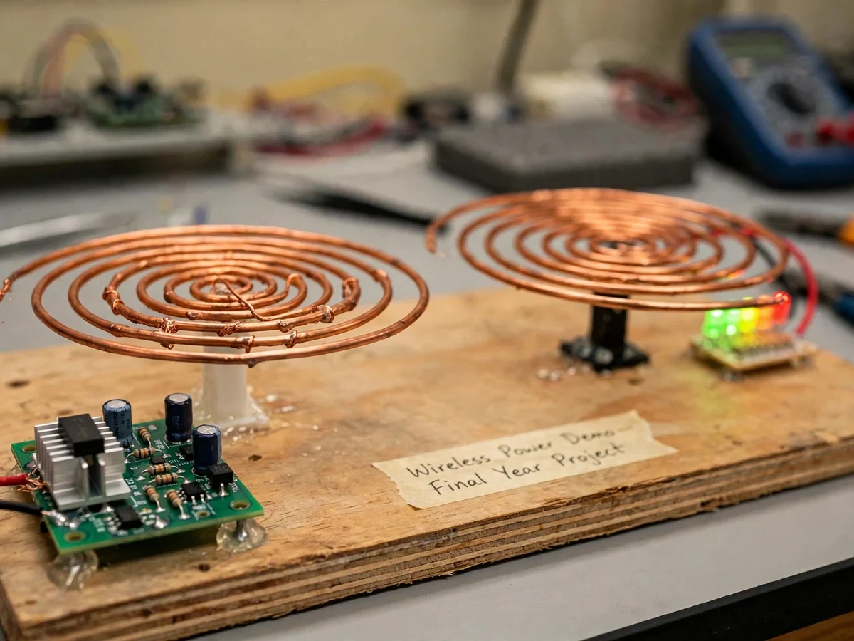
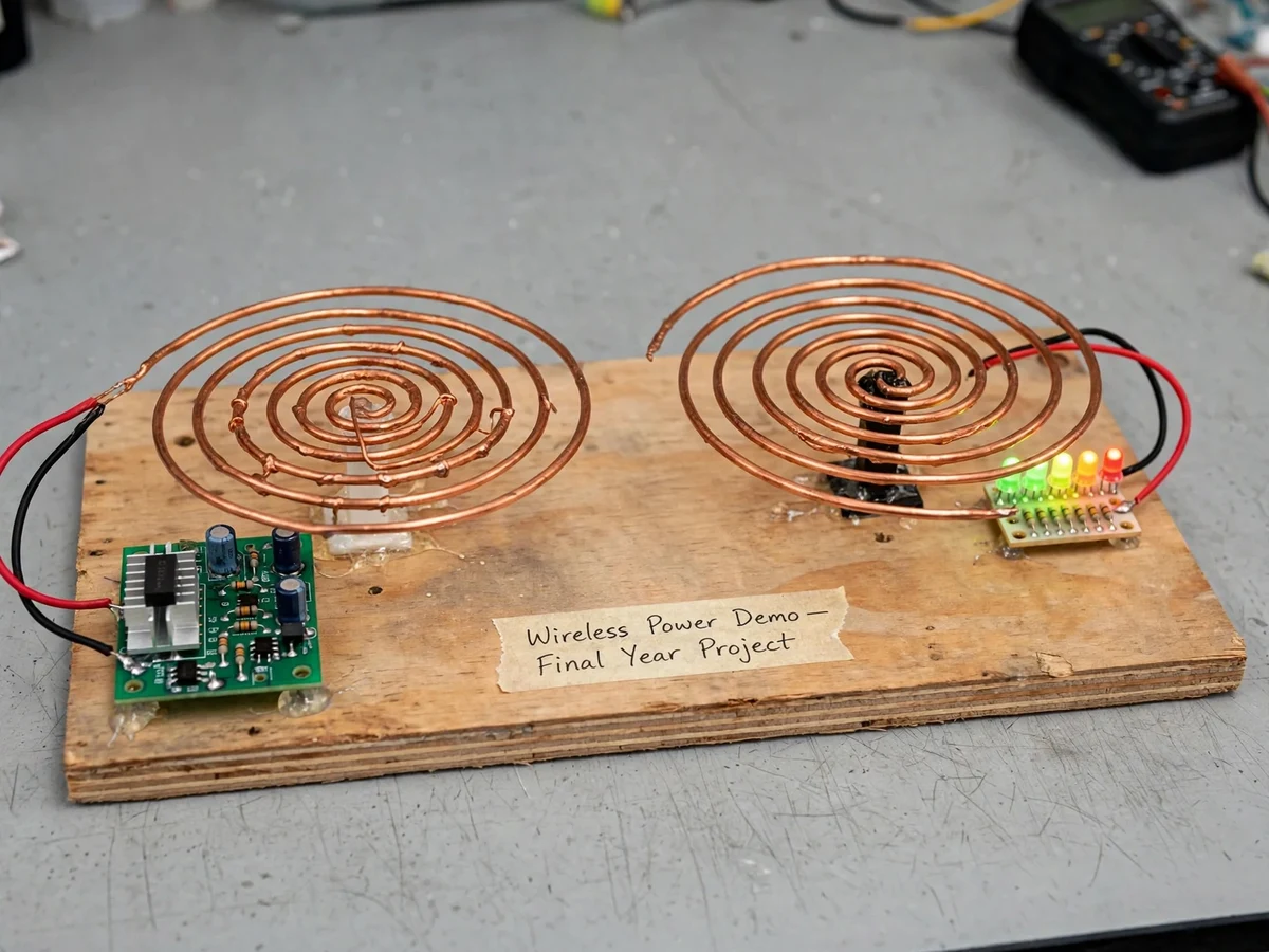
Running a wire to every load is not always possible or desirable — sensors on rotating machinery, sealed enclosures and charging pads all motivate transferring power without conductors. Microwave power transmission takes this idea to its extreme: RF energy is generated, radiated, captured by a receiving element and rectified back to DC. The underlying resonance principle goes back over a century, and the concept is still researched for applications from wireless device charging to space-based solar power. This project distills that concept into a safe benchtop prototype. A transistor-based RF oscillator drives a hand-wound transmitter coil; a second coil, tuned to the same resonant frequency, couples to its field, and a rectifier board converts the received energy to light an LED array — with no wired connection between the two sides. Because the output is visible on the LEDs, coupling versus coil gap and tuning can be measured directly with a multimeter, giving the report real numbers from the student's own calibration. This is a built-to-order hardware project: the prototype is assembled, wired and tuned fresh for your order.
How it works
- A 12 V DC supply powers the transistor oscillator PCB, which produces an RF-range alternating current at the tuned LC frequency.
- The current flows through the hand-wound transmitter coil, producing an oscillating magnetic field around it.
- The receiver coil — wound and tuned to the same resonant frequency — couples to that field and develops an induced voltage.
- A rectifier on the receiver board converts the induced AC into DC, which drives the LED array.
- Changing the coil gap or lateral alignment changes the coupling, and the LEDs visibly brighten or dim — the core measurement for the report.
- The included calibration procedure uses a multimeter to record supply current and LED behavior at several gaps, producing the transfer curve honestly from the student's own build.
Tech stack:
- Transistor-based RF oscillator PCB (LC tuned driver)
- Hand-wound resonant copper coil pair (transmitter + receiver)
- Receiver rectifier board with LED array load
- 12 V DC regulated power supply
- Plywood mounting base with hookup wiring
- Digital multimeter (measurement & calibration)
- Soldering iron and basic hand tools
| Parameter | Value |
|---|---|
| Driver | Transistor LC RF oscillator; frequency set by coil/capacitor values (design target: tens to hundreds of kHz) |
| Coupling | Resonant inductive, hand-wound copper coils |
| Transfer distance | 2–5 cm coil gap (design target; verified during buyer calibration) |
| Load | LED array via receiver rectifier (low-power demonstration load only) |
| Supply | 12 V DC regulated |
| Efficiency | Not pre-claimed — measured by the buyer with the included multimeter procedure; depends on winding quality, alignment and tuning |
| Base | Plywood mounting board with labeled wiring |
Project features
- [Resonant coil pair] Two hand-wound copper coils tuned to the oscillator frequency; transmitter and receiver are matched for maximum coupling at the design gap.
- [RF oscillator driver] A transistor-based LC oscillator PCB generates the drive signal; tuning points are documented so resonance can be matched during assembly.
- [Wireless LED load] The receiving coil feeds a rectifier and LED array that lights with no wired connection to the source — the demo's visible proof of transfer.
- [Gap-dependent output] LEDs brighten and dim as the coil gap changes, making the distance dependence of coupling directly measurable.
- [Tuning and calibration procedure] Step-by-step instructions for coil spacing, resonance matching and multimeter readings, so the report's numbers come from the buyer's own bench.
- [Safe low-power RF design] The benchtop build runs at low voltage and low power — no magnetron, no high-voltage RF stage, no special shielding needed.
- [Rectifier receiver board] Converts the received AC to DC for the LED load, demonstrating the rectification stage of the power-beaming chain.
What is included
- Assembled and tuned working prototype (oscillator PCB, coil pair, receiver/LED board on plywood base)
- Oscillator schematic and tuning notes
- Circuit/wiring documentation with labeled connection diagram
- Coil winding and resonance-tuning procedure
- Component list with sourcing notes
- Multimeter-based measurement/calibration procedure
- Project report PDF (background, methodology, the student's own measured transfer data, error discussion)
- PPT presentation for final review
- Viva Q&A preparation document (resonance, inductive coupling, rectification, microwave power-beaming concepts)
Limitations & prerequisites
- Short range: the design target is a 2–5 cm coil gap; output falls off sharply with distance — that falloff is the physics being demonstrated.
- Low power: the build lights an LED array only. It cannot charge phones or power appliances; it is a demonstration, not a power supply.
- Efficiency is not pre-claimed. It is measured during the buyer's own calibration and depends on coil winding quality, alignment and tuning.
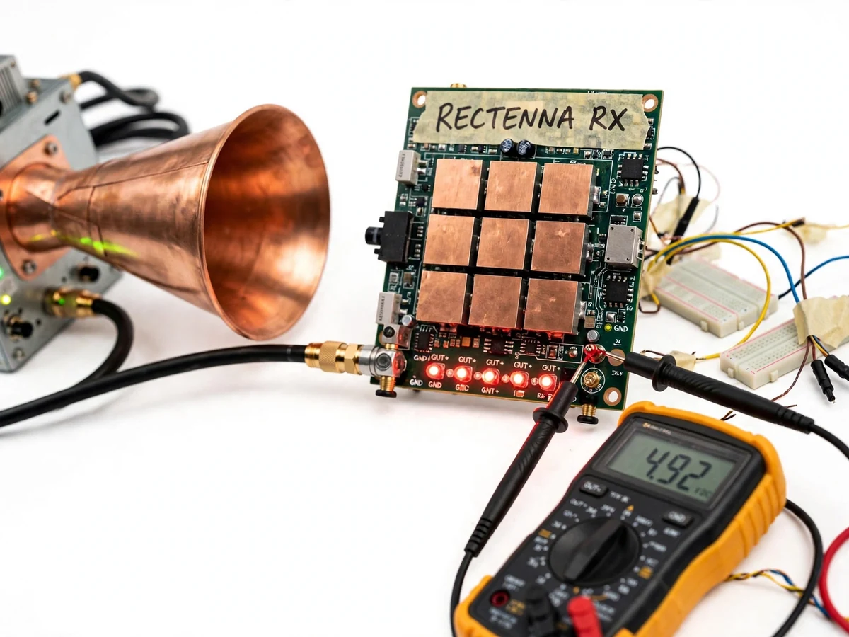
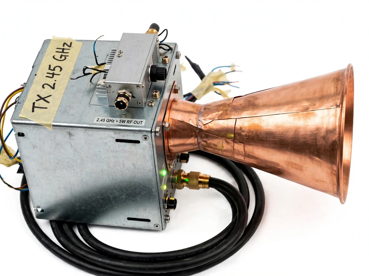
- This benchtop build demonstrates the source → coupling → rectification chain at safe low-power RF frequencies. It is not a 2.45 GHz magnetron system and does not demonstrate far-field microwave beaming. (A true 2.4 GHz source-and-rectenna variant is possible as a customization.)
- Output is sensitive to coil alignment; lateral misalignment reduces LED brightness quickly.
- The prototype is not a certified or commercial wireless charger.
Frequently Asked Questions
Which controller is used?
None — this is an all-analog build. The drive stage is a transistor-based LC oscillator; there is no microcontroller or firmware.
Is it really microwave frequency?
The title refers to the microwave power-beaming concept the project demonstrates: RF generation, resonant coupling and rectification. The benchtop build implements that chain at safe low-power RF frequencies rather than 2.45 GHz. A true 2.4 GHz source-and-rectenna variant can be built as a customization.
What power supply is needed?
A regulated 12 V DC supply drawing only a few amps at most. A bench supply or a 12 V adapter both work; the report documents the current drawn during the student's calibration.
How far can it transmit power?
The design target is a 2–5 cm gap between the coils. Beyond that the LED brightness drops off quickly — measuring that falloff is part of the experiment.
What are the main limitations?
Short range, LED-scale power only, no pre-claimed efficiency (measured by the student), and alignment sensitivity. Full detail is in Limitations & Prerequisites above.
Is this project suitable for a final-year project?
Yes — for Electrical and Electronics Engineering programs. It demonstrates resonance, inductive coupling, RF oscillators and rectification, and the report is built on the student's own measured transfer data, which is strong viva material. Suitable for B.E./B.Tech final-year projects in Electrical and Electronics Engineering.
Components & software requirements
- Transistor-based RF oscillator PCB (LC tuned driver)
- Hand-wound resonant copper coil pair (transmitter + receiver)
- Receiver rectifier board with LED array load
- 12 V DC regulated power supply
- Plywood mounting base with hookup wiring
- Digital multimeter (measurement & calibration)
- Soldering iron and basic hand tools
Delivery information
Built-to-order project. Delivery timeline is shared after order confirmation based on current queue.
Support terms
Complete documentation, setup guide, and viva preparation included. Support for setup and explanation provided.