
More project photos (3)
The problem
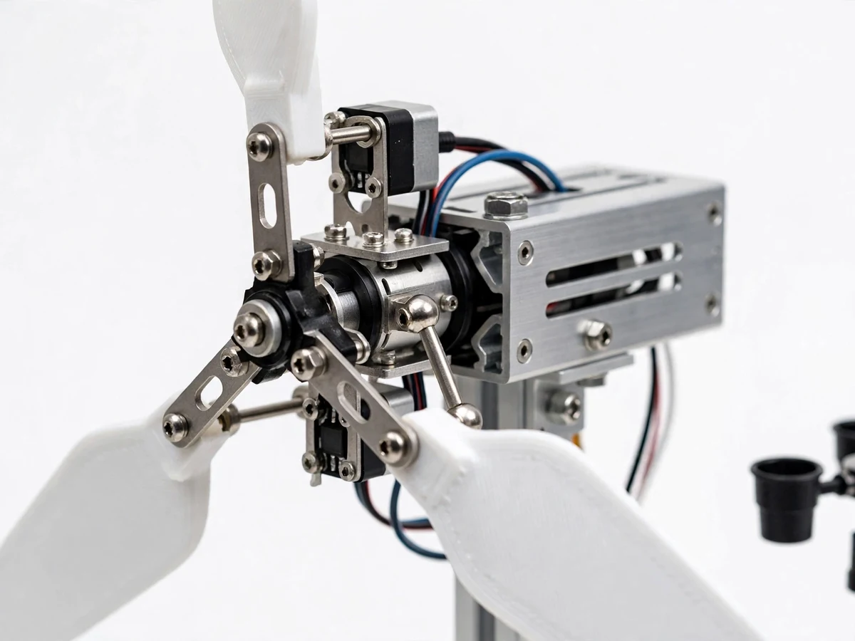
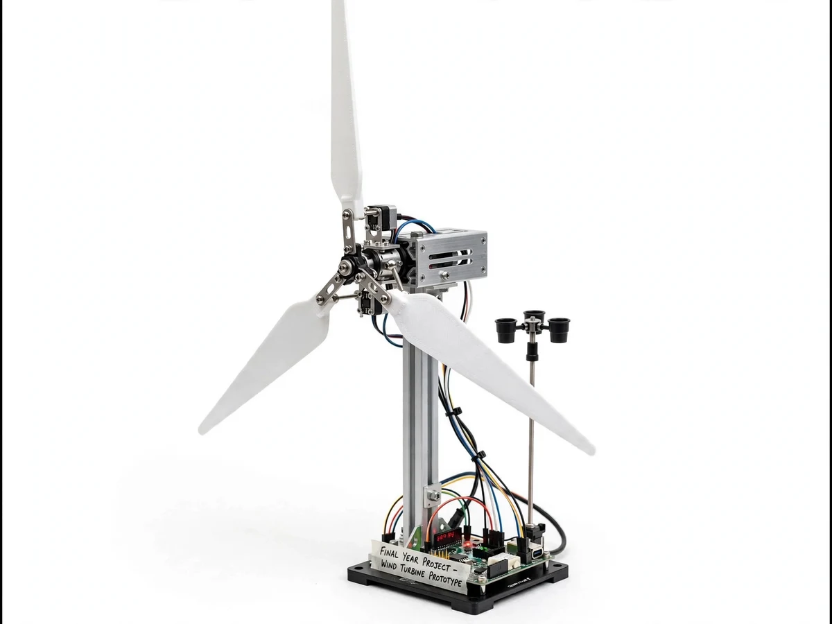
Small wind is the poor relation of the renewables lab: solar PV gets panels, simulators and MPPT trainers, while wind is usually a poster on the wall. What students miss is the control problem at the heart of every real turbine — the rotor must be protected from overspeed without being stalled in light air, and modern machines solve it with blade pitch control. The engineering gap is a working, affordable model that demonstrates pitch logic hands-on: how pitch angle, wind speed, rotor speed and electrical output relate, with the mechanism visible and adjustable. This project fills it with a bench-scale horizontal-axis turbine: 3D-printed or PVC blades on a hub with servo-driven pitch linkages, a tower and nacelle, an anemometer measuring wind speed, an RPM pickup, and a small DC generator with a rectifier and charge circuit. A microcontroller reads wind speed and commands the pitch servos, so the student can demonstrate the full operating logic — including feathering above the rated wind speed.
Cup anemometer reporting the live wind speed the rotor sees to the controller.
Follow the working sequence
How it works
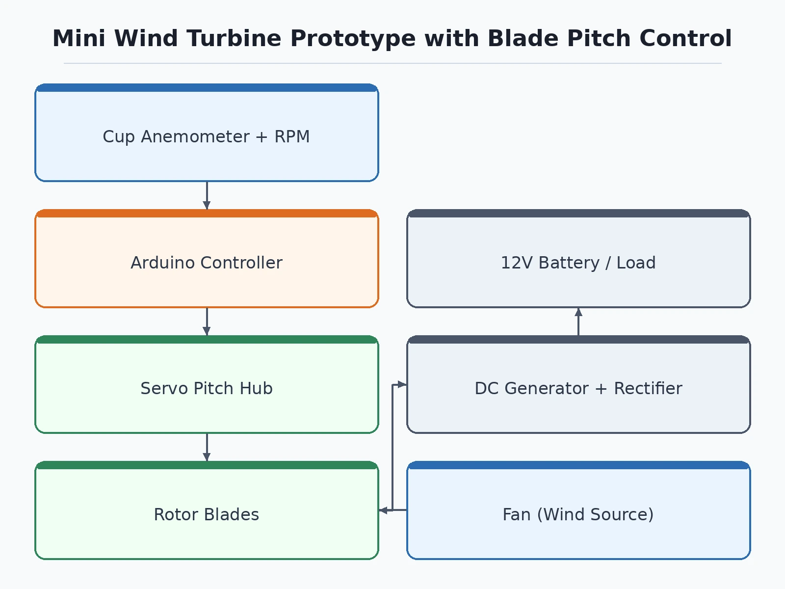
- Wind (or a fan in the lab) drives the 3-blade rotor; the cup anemometer reports wind speed to the microcontroller.
- The RPM pickup counts rotor revolutions and the controller computes tip-speed behavior against the measured wind.
- Below the cut-in wind speed the controller holds the blades fine and the generator output is negligible; the student records this as the cut-in point.
- In the operating band the controller trims pitch for the best RPM for the measured wind, and the generator charges the battery through the rectifier/regulator.
- Above the rated wind speed the controller feathers the blades progressively, holding rotor speed within the safe design band while the student watches RPM cap out.
- During the test procedure the student logs voltage, current and RPM at stepped fan distances, producing their own power curve for the report.
Tech stack:
- Arduino-class microcontroller (control firmware)
- 3D-printed / PVC rotor blades (3-blade horizontal-axis design)
- Servo-driven pitch linkage hub
- Cup anemometer (wind-speed input)
- Hall-effect / IR RPM pickup
- Small DC generator with rectifier + charge regulator
- Steel/Aluminium tower and nacelle frame
- Arduino IDE (C/C++ firmware)
- Test procedure with fan wind source and multimeter logging sheets
| Parameter | Value |
|---|---|
| Rotor | 3 blades, design tip diameter ~60–80 cm (fabrication drawing dimensioned) |
| Blades | FDM 3D-printed or PVC sheet, replaceable; hub with servo pitch linkage |
| Pitch range | Approximately 0–90° from fine to fully feathered (servo-driven) |
| Wind input | Cup anemometer; design operating range 2–10 m/s (demonstration band) |
| Rotor speed | Hall/IR pickup; overspeed protection by feathering above rated wind speed |
| Generator | Small DC machine as generator; rectifier, smoothing and 12 V charge regulator |
| Control modes | Cut-in hold, operating-band pitch trim, overspeed feathering |
| Power output | No claimed figures at build — the student measures and reports their own V/I/RPM curve |
| Structure | Metal tower and nacelle frame; guyed or weighted base for lab use |
Project features
- [Servo blade pitch control] Each blade's pitch is driven by a servo through a linkage, giving the full operating range from fine pitch (power capture) to feathered (overspeed protection).
- [Anemometer wind-speed input] A cup anemometer feeds live wind speed to the controller, so pitch responds to the actual airflow the rotor sees, not a guess.
- [RPM sensing] A Hall-effect or IR pickup counts rotor revolutions, letting the controller and the student close the loop on rotor speed.
- [Three operating modes] Firmware implements cut-in logic, variable-pitch power tracking, and feathering above the rated wind speed — the same states a utility turbine controller manages.
- [DC generator and charge circuit] A small DC motor run as a generator feeds a rectifier, smoothing capacitor and charge regulator for a 12 V battery or load bank.
- [Adjustable blade geometry] Blades are designed for FDM printing or PVC sheet, and the hub allows the student to test different pitch schedules and re-run their measurements.
- [Student-measured performance] The kit includes a test procedure (fan as wind source, multimeter + tachometer readings) so every power-vs-wind-speed point in the report is the student's own data.
What is included
- Working mini wind-turbine prototype (rotor, pitch hub, tower, nacelle, generator, charge circuit)
- Pitch-control firmware source code (modes, thresholds, servo mapping)
- Fabrication drawings and blade-printing files
- Wiring and control documentation
- Wind-tunnel (fan) test procedure with logging sheets
- Component list with ratings
- Project report PDF (wind theory, pitch control, methodology, student's own test data)
- PPT presentation for final review
- Viva Q&A preparation document (aerodynamics basics, pitch vs stall control, tip-speed ratio)
- Setup and demonstration guide
Limitations & prerequisites
- This is a tabletop teaching model, not a power plant: no power-output figures are claimed at build, and lab fan airflow is not laminar wind — measured values are for comparative study, not field prediction.
- The anemometer reads the local airflow at the rig; indoor fan tests give turbulent, uneven flow, which the report must acknowledge when presenting curves.
- Feathering protects the model rotor, but the structure is a light lab build and must not be flown outdoors in real wind — it is not weatherproof or guyed for storms.
- Blade balance and hub strength are student-verified during the build; an unbalanced rotor at speed vibrates, so the assembly checklist is part of the kit.
- 3D-printed blades are demonstration parts: they flex and their airfoil is approximate, not a certified blade profile.
Frequently Asked Questions
Does it generate usable power?
It generates measurable electrical output into a battery or load bank, but this is a control-study model, not a charger product — the deliverable is the pitch-control demonstration and your own measured data, not a wattage claim.
How is blade pitch controlled?
A servo on the hub drives the pitch linkages; the microcontroller reads wind speed from the anemometer and rotor speed from the pickup, then commands pitch through the cut-in, operating and feathering states.
What wind source is used for testing?
A standard table/pedestal fan at stepped distances, with the anemometer recording the actual wind speed at the rotor plane for each reading.
Can blade geometry be changed?
Yes — the blades are printable/swappable and the hub supports re-testing, so different pitch schedules or blade shapes can be compared in the report.
Can it be installed on a rooftop?
No. It is an indoor lab model; it is not weatherproof, not certified, and not designed for real-wind structural loads.
Is this project suitable for a final-year project?
Yes — for Mechanical and renewable-energy programs. It demonstrates aerodynamics, mechanisms (pitch linkage), embedded control and honest experimental method. Suitable for B.E./B.Tech final-year projects in Mechanical and Renewable Energy engineering.
Components & software requirements
- Arduino-class microcontroller (control firmware)
- 3D-printed / PVC rotor blades (3-blade horizontal-axis design)
- Servo-driven pitch linkage hub
- Cup anemometer (wind-speed input)
- Hall-effect / IR RPM pickup
- Small DC generator with rectifier + charge regulator
- Steel/Aluminium tower and nacelle frame
- Arduino IDE (C/C++ firmware)
- Test procedure with fan wind source and multimeter logging sheets
Delivery information
Built-to-order project. Delivery timeline is shared after order confirmation based on current queue.
Support terms
Complete documentation, setup guide, and viva preparation included. Support for setup and explanation provided.
Download free synopsis (PDF)
Enter your name and WhatsApp number — the synopsis PDF downloads immediately. We may send occasional project updates on WhatsApp; no spam.