
More project photos (2)
The problem
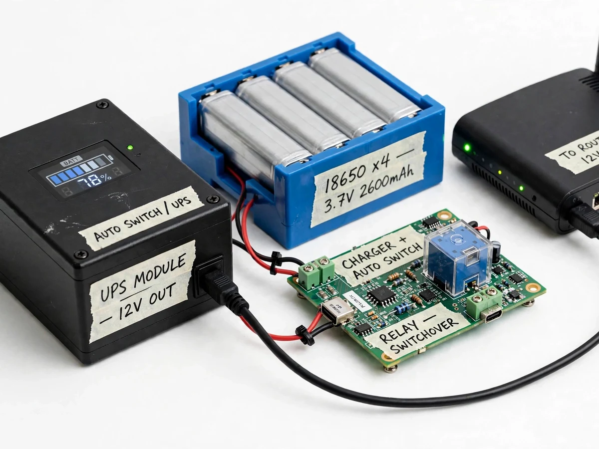
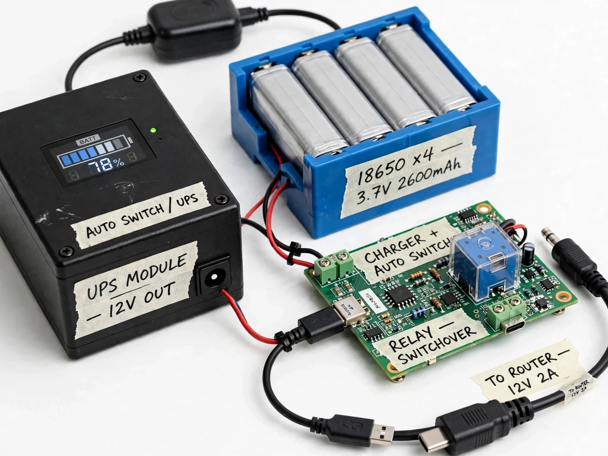
A Mini UPS for a WiFi router is a small battery backup unit that keeps a home router powered when mains electricity fails, so internet access continues through short power cuts instead of dropping the moment the lights go out. The unit sits between the wall adapter and the router, charging its battery pack while mains power is present and taking over the router load automatically when mains power disappears. During a power cut the router reboots, video calls freeze, online classes disconnect, and devices spend several minutes reconnecting once power returns. A full-size computer UPS is oversized, noisy, and wasteful for a single low-power router, while a plain power bank usually cannot charge and supply a load at the same time and often interrupts power when it switches modes. The gap this build closes is a compact, always-connected backup sized for one router, with a visible battery level showing how much backup remains.
12 V DC supply derived from mains power.
Follow the working sequence
How it works
The Mini UPS for a WiFi router works as a continuous power path with two sources and one output: mains power feeds the router and charges the battery pack at the same time, and the battery pack feeds the router the moment mains power fails. A mains adapter supplies the charger board, which charges four 18650 lithium-ion cells through a protection circuit guarding against overcharge, over-discharge, and short circuits. A relay-based switchover board watches the mains side; while mains power is present it passes mains-derived power to the router, and when mains power drops it switches the output to a boost converter that steps the battery voltage up to the 12 V the router needs. The changeover happens fast enough that the router keeps running without rebooting, and a small display shows the battery level in bars and percent, showing remaining backup. When mains power returns, the relay switches back and the charger resumes topping up the battery pack.
- The mains adapter feeds the charger board, which charges the 18650 pack while the router runs on mains-derived power through the switchover relay.
- The protection circuit continuously guards the pack against overcharge, over-discharge, and short circuits, disconnecting the pack if any limit is crossed.
- The battery level display reads the pack voltage and converts it to bars and percent, with status LEDs showing mains, battery, or charging state.
- When mains power fails, the relay drops out and connects the boost converter output to the router, stepping the pack voltage up to a regulated 12 V.
- The router keeps running on battery power without rebooting, and the display shows the falling pack level so the user knows how much backup remains.
- When mains power returns, the relay switches the router back to mains-derived power and the charger board resumes charging the pack.
- The builder verifies the unit with a mains-interruption test: the mains adapter is unplugged while the router runs, and the router must stay online with its indicator lit throughout.
Builder note (original build detail): the relay coil is powered from the mains-derived side, never from the battery side, or the relay would drain the pack while waiting for an outage; and the display sense wire taps the pack after the protection board, not before it, so a pack that the protection circuit has disconnected does not read as a live voltage.
Tech stack:
- 18650 lithium-ion cells in 2-series 2-parallel arrangement
- Lithium-ion charger board with balance and protection circuit
- Relay-based automatic switchover board
- DC-DC boost converter to regulated 12 V output
- Battery level display module (bars and percent)
- Mains adapter input with DC barrel output cable
- Status LEDs for mains, battery, and charging states
- Compact enclosure with labelled input and output sockets
| Parameter | Value |
|---|---|
| Output voltage | 12 V regulated (design target) |
| Output current | Up to 2 A maximum (design target) |
| Input supply | 12 V DC mains adapter, 2 A rating (design input) |
| Battery pack | 4 × 18650 cells in 2-series 2-parallel arrangement (design configuration) |
| Pack voltage | 7.4 V nominal (design value, from 3.7 V nominal per cell) |
| Pack capacity | 5200 mAh (design calculation, from 2600 mAh per cell in 2-parallel) |
| Cell voltage | 3.7 V nominal, 4.2 V full charge (datasheet values) |
| Protection cutoff | Approximately 3.0 V per cell (protection board design value) |
| Switchover | Relay-based automatic changeover (design target: no router reboot during changeover) |
| Battery display | Bars and percent from pack voltage (design implementation) |
| Expected backup | Approximately 4–5 hours at an assumed 6 W router load (design estimate, not a measured claim; actual runtime varies with router load and cell condition) |
| Output connector | 5.5 mm × 2.1 mm DC barrel jack (design configuration; check the router adapter before ordering) |
| Enclosure | Compact bench enclosure, approximately 150 mm × 100 mm × 60 mm (design target) |
Project features
The Mini UPS for a WiFi router is built around four capabilities that matter most in daily use: automatic switchover that keeps the router alive through a mains failure, a battery level display that shows remaining backup before and during an outage, safe lithium-ion charging with protection against overcharge and short circuits, and a regulated 12 V output matched to a standard home router. Around those four capabilities the build adds practical touches: a compact enclosure that sits beside the router, a standard DC barrel output cable so no router modification is needed, and clear status LEDs that show at a glance whether the unit is on mains power, on battery, or charging. Together these capabilities turn a simple battery pack into a dependable household backup: the router stays online, the user always knows the backup state, and the battery is treated safely enough for everyday use in a home.
- [Automatic switchover] A relay board watches the mains-derived supply and switches the router load to battery power the moment mains power fails, then switches back when mains power returns, with no manual step and no router reboot as the design target.
- [Battery level display] A small display shows the pack level in bars and percent, so the user can check remaining backup before an outage and watch it fall during one, instead of discovering an empty pack mid-cut.
- [Protected lithium-ion charging] The charger board and protection circuit guard the pack against overcharge, over-discharge, and short circuits, and charging resumes automatically once mains power returns.
- [Regulated 12 V router output] A boost converter steps the battery pack voltage up to a regulated 12 V output matched to a standard home router, delivered through a normal DC barrel cable with no router modification.
- [Mains and battery status LEDs] Separate LEDs show whether the unit is running on mains power, running on battery, or charging, so the operating state is readable across the room without checking the display.
- [Compact home enclosure] The charger board, switchover relay, display, and battery pack are housed in a small enclosure that sits beside the router, with labelled input and output sockets and accessible wiring for demonstration.
- [Router-agnostic DC output] The output suits any router that runs on a 12 V DC barrel input within the stated current limit, so the same unit can be demonstrated with different home routers.
Optional customization (not in the base build): a 9 V output tap for routers that use a 9 V adapter, and a buzzer that sounds when the unit switches to battery. Future scope (not implemented): a low-battery warning message over Wi-Fi, and solar charging input.
What is included
- Assembled Mini UPS unit: charger board, switchover relay board, boost converter, battery pack, level display, LEDs, and enclosure
- DC output cable with barrel connector for a standard 12 V router
- Wiring diagram and assembly layout with the mains-interruption test procedure
- Component list with sourcing notes for the cells, charger board, relay board, and display
- Project report PDF (power-path design, charging and protection, switchover logic, honest limits)
- PPT presentation for final review
- Viva Q&A preparation document (lithium-ion safety, relay switchover, boost conversion, why a power bank is not a UPS)
Limitations & prerequisites
- The unit suits routers that run on a 12 V DC barrel input within the stated 2 A current limit; routers needing 9 V, 5 V over USB, or fibre ONT power over a different connector are out of scope for the base build.
- Backup duration is an estimate, not a promise: it falls with a hungrier router, older cells, cold conditions, and converter losses, and the report states the assumed 6 W load behind the estimate.
- The battery level display reads pack voltage, so its percent figure is an approximation: lithium-ion voltage stays flat across most of the discharge curve and drops steeply near empty, so the last bars fall faster than the first.
- A relay changeover is not an online double-conversion UPS: the design target is no router reboot, but routers with unusually sensitive power inputs may still restart, and the builder test procedure exists to catch that case before submission.
- The prototype is a household backup for one router, not a certified mains safety device: mains wiring stays inside the factory adapter, and the student build works only on the low-voltage DC side.
- Lithium-ion cells demand respect: damaged, swollen, or unmatched cells must never be used, and the pack must not be charged unattended with a bypassed protection board.
Timeline
- Week 1: component sourcing and pack assembly — cells matched, holder wired, protection board fitted, and charger board bench-tested without a load.
- Week 2: switchover and output stage — relay board wired, boost converter set to a regulated 12 V output, display calibrated against pack voltage, enclosure fitted.
- Week 3: integration and mains-interruption testing — router connected, mains-failure and mains-return tests run, backup estimate checked against the stated assumptions, report and PPT drafted.
- Week 4: documentation and viva preparation — wiring diagram finalised, report completed, PPT and Q&A document prepared, unit demonstrated end to end.
Support
- Setup guidance covers connecting the unit between the mains adapter and the router, checking the router adapter rating against the 12 V and 2 A limits, and reading the display and LEDs.
- Demonstration support covers the mains-interruption test procedure and how to explain the power path, the protection circuit, and the display approximation honestly in a viva.
- Fault guidance covers the common build faults: a relay wired to the battery side, a display sense wire tapped before the protection board, and a boost converter set above 12 V.
Frequently Asked Questions
How does the automatic switchover work?
The relay board watches the mains-derived supply and holds the router on mains power while it is present. When mains power fails, the relay drops out and connects the boost converter output to the router, so the battery pack takes over the load. When mains power returns, the relay switches the router back and the charger resumes charging the pack. The changeover is designed to happen without the router rebooting, which is verified with the mains-interruption test in the build procedure.
What does the battery level display actually show?
The display converts the battery pack voltage into bars and a percent figure, giving a quick read on remaining backup before and during an outage. It is an approximation, not a fuel gauge: lithium-ion voltage stays fairly flat for most of the discharge and falls steeply near empty, so the last bars drop faster than the first. The report explains this honestly, and the display is paired with status LEDs so the operating state is visible at a glance.
Will it work with my router?
It works with routers that run on a 12 V DC barrel input and draw within the stated 2 A current limit, which covers most standard home routers. The check is simple: read the router adapter label for its output voltage and current before ordering. Routers needing 9 V, USB power, or a different connector need the optional 9 V tap or a different output cable, which are customization options rather than part of the base build.
How long will the router stay online during a power cut?
The design estimate is approximately 4–5 hours at an assumed 6 W router load, calculated from the 5200 mAh pack and an allowance for converter losses. That figure is an estimate with stated assumptions, not a measured promise: a hungrier router, older cells, or a cold room shortens it, and a lighter load lengthens it. The report shows the calculation openly so the estimate can be defended rather than merely quoted.
Why not just use a power bank for the router?
Most power banks cannot charge and supply a load at the same time, and many interrupt their output when they switch between charging and discharging, which reboots the router. A Mini UPS is built for the opposite job: it stays connected in the power path permanently, passes mains-derived power through while charging, and takes over instantly on mains failure. It also adds a visible battery level and a regulated 12 V output matched to the router, which a generic power bank does not provide.
Is this project suitable for a final-year project?
Yes — for Electrical and Electronics degree and diploma programs, because it combines power electronics, battery charging and protection, relay control logic, and DC-DC conversion in one working household device. It gives a live demonstration that examiners can test by unplugging the mains adapter, and its honest limits — the display approximation, the runtime estimate, and the relay changeover — make for strong viva discussion. The report, wiring diagram, and test procedure give the student documented evidence for every claim made about the build.
Components & software requirements
- 18650 lithium-ion cells in 2-series 2-parallel arrangement
- Lithium-ion charger board with balance and protection circuit
- Relay-based automatic switchover board
- DC-DC boost converter to regulated 12 V output
- Battery level display module (bars and percent)
- Mains adapter input with DC barrel output cable
- Status LEDs for mains, battery, and charging states
- Compact enclosure with labelled input and output sockets
Delivery information
Built-to-order project. Delivery timeline is shared after order confirmation based on current queue.
Support terms
Complete documentation, setup guide, and viva preparation included. Support for setup and explanation provided.
Download free synopsis (PDF)
Enter your name and WhatsApp number — the synopsis PDF downloads immediately. We may send occasional project updates on WhatsApp; no spam.