
More project photos (2)
The problem
Series-connected lead-acid batteries drift apart in voltage even when they are bought together and used as one bank. A lead-acid battery equalizer for series banks fixes this drift by moving charge between the units so that all of them stay near the same voltage, instead of letting the strongest unit take the most charge and the weakest fall further behind on every cycle. The drift happens because no two units are truly identical: tiny differences in plate area, electrolyte quantity and internal resistance mean the same series current leaves each unit at a slightly different state of charge, and the gap widens a little with every charge and discharge cycle. Left alone, the weak unit is repeatedly over-discharged while the strong unit is repeatedly over-charged, which shortens the life of the whole bank. This project builds a working equalizer with a live per-unit voltage display, so the imbalance and the correction can both be seen happening.
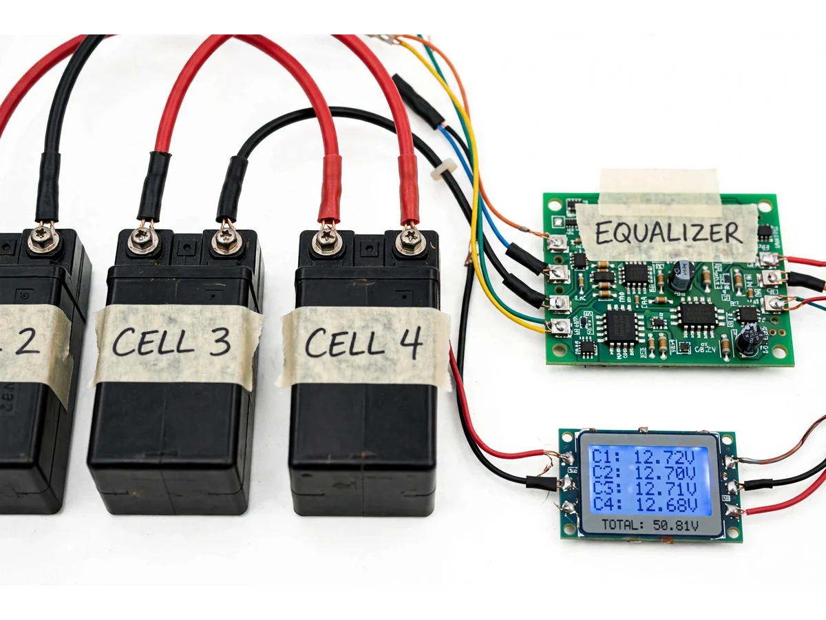
A bank total reading alone hides this problem completely. A 48 V bank can read a healthy-looking total while one unit inside it is already lagging, because the stronger units cover for it in the sum. That is why this build measures and displays every unit separately: the display is the diagnostic instrument, and the equalizer is the correction. Builder note from the assembly: the display was wired to read each unit separately rather than the bank total alone, precisely because a single total reading can look healthy while one unit is already falling behind. The distinction matters for the viva too. This is an equalizer, not a charger and not a protection board: it does not supply charging energy, and it does not cut power on over-voltage or under-voltage the way a battery management system does. It only redistributes charge that is already in the bank, keeping the units even so the bank ages evenly.
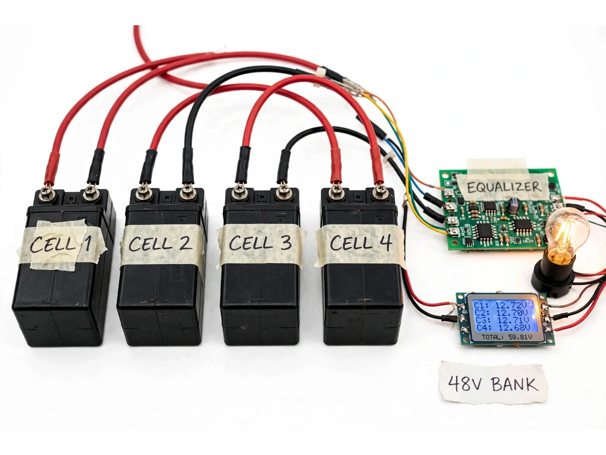
Four 12 V units wired in series form a 48 V bank.
Follow the working sequence
How it works
The lead-acid battery equalizer for series banks works by continuously watching every unit in the bank and shifting charge from the strongest to the weakest until their voltages match. Sense wires carry each unit's voltage to the equalizer board, which compares all four readings and switches a small transfer stage on for the unit that is running high. Charge is moved across to the unit running low rather than being burned off as heat, so the energy stays inside the bank. The display refreshes with each unit's voltage and the bank total, letting anyone watching see the spread narrow as the equalizer works. The process runs during charging and during discharge, and it repeats automatically whenever the gap between units grows again. The equalizer does not charge the bank and does not cut power like a protection board: an external charger still supplies the energy, and the equalizer only keeps it shared evenly.
- Four 12 V sealed lead-acid units are wired in series to form a 48 V demonstration bank, with a bulb connected as a safe, visible discharge load.
- A separate sense wire from each unit's terminals carries that unit's voltage back to the equalizer board, so the board sees four individual readings rather than one bank total.
- The board compares the four readings and identifies the highest-voltage and lowest-voltage units, starting redistribution when the spread crosses its design threshold.
- A switching transfer stage moves charge from the highest unit toward the lowest unit, instead of bleeding the excess off as heat through a resistor.
- The display updates with all four unit voltages and the bank total, so the narrowing spread is visible live while the equalizer works.
- The cycle repeats automatically: whenever charging or discharging opens the gap again, the board resumes transferring charge until the units are back in step.
Tech stack:
- Sealed lead-acid batteries · 12 V units
- Equalizer board · switching transfer stage
- Voltage display module · per-unit readout
- Copper wiring · series interconnections
- DC bulb load · demonstration discharge
- Multimeter · verification instrument
- Soldering station · prototype assembly
- Terminal connectors · bank wiring
| Parameter | Value |
|---|---|
| Bank configuration | 4 units in series (demonstration bank) |
| Nominal bank voltage | 48 V (nominal rating) |
| Unit rating | 12 V nominal per unit (standard rating) |
| Internal cells per unit | 6 cells of nominal 2.0 V each (standard lead-acid value) |
| Display channels | 4 unit channels plus bank total (design specification) |
| Balance start threshold | 0.1 V spread between units (design target) |
| Balance transfer current | Up to 1 A per channel (design target) |
| Display refresh | Approximately 1 reading per second (design target) |
| Demonstration load | 1 DC bulb (demonstration load) |
| Equalizer function | Charge redistribution only — not a charger and not a protection cut-off (design scope) |
Project features
The lead-acid battery equalizer for series banks combines three capabilities that make the balancing visible and testable: active charge redistribution between units, a live per-unit voltage display, and a complete demonstration bank that can be charged, loaded and measured. Charge redistribution moves energy from the highest-voltage unit to the lowest instead of wasting it, which is the core of the project and the part an examiner can verify by watching the display. The voltage display shows all four units side by side with the bank total, so imbalance is obvious immediately without needing a multimeter. The demonstration bank itself, four 12 V units wired in series with a bulb load, turns the idea into a bench experiment: imbalance can be created deliberately, and the equalizer's correction can be observed and recorded.
- [Active charge redistribution] The equalizer board transfers charge from the highest-voltage unit to the lowest-voltage unit through a switching stage, rather than burning excess energy as heat. Implemented in the prototype.
- [Per-unit voltage display] A display module shows all four unit voltages together with the bank total, updated live, so imbalance and correction are visible without extra instruments. Implemented in the prototype.
- [Imbalance demonstration setup] The four-unit series bank with a bulb load lets the builder deliberately create imbalance, then watch the equalizer close the gap during charge and discharge. Implemented in the prototype.
- [Sense-wire measurement] Each unit is measured through its own sense wires, so the board acts on true per-unit voltages instead of an averaged bank reading. Implemented in the prototype.
- [Wiring and safety guide] The build documentation covers series wiring order, sense-wire connections, polarity checks and safe handling of a 48 V bank, so the prototype can be assembled and demonstrated without guesswork. Included with the build.
- [Optional imbalance alarm] A buzzer or indicator output that sounds when the spread between units crosses a set limit, for benches where the display is not watched continuously. Optional add-on, not fitted by default.
- [Extended channel count] Future scope: adapting the board layout to banks of more than four units, which needs one additional sensing and transfer channel per extra unit. Future scope, not part of the delivered build.
What is included
- Equalizer board assembled and wired to the four-unit series bank
- Per-unit voltage display module showing all four units and the bank total
- Four 12 V sealed lead-acid units with series interconnections and terminals
- Demonstration DC bulb load with holder and wiring
- Wiring diagram, series-connection guide and polarity-check checklist
- Project report PDF (problem, mechanism, circuit explanation, test procedure, results tables left for the builder's own readings)
- PPT presentation for final review
- Viva Q&A preparation document (series drift, equalization vs protection, lead-acid behaviour, display interpretation)
Limitations & prerequisites
- The equalizer redistributes charge already present in the bank; it cannot recharge a flat bank and cannot replace an external charger.
- It provides no over-voltage, under-voltage or short-circuit cut-off — that protection role belongs to a separate battery management or protection board, which this project deliberately is not.
- Balancing speed is limited by the design-target transfer current, so a deeply imbalanced bank takes time to converge; no convergence time is claimed without the builder's own test readings.
- The demonstration bank uses small sealed lead-acid units; the board is not rated for traction, inverter or vehicle-scale banks.
- Display readings are indicative bench readings, not calibrated laboratory measurements, and the report records the builder's own readings rather than pre-filled results.
Frequently Asked Questions
How is this different from a battery charger?
A charger supplies energy to the bank from the mains, while this equalizer only moves energy that is already inside the bank between its units. The equalizer cannot recharge a flat bank on its own and always works alongside an external charger, which remains a separate piece of equipment. Think of the charger as filling the bank and the equalizer as keeping the filling even across all four units.
Is this the same as a battery management system (BMS)?
No. A battery management or protection board monitors limits and cuts power when a cell goes over-voltage, under-voltage or into a fault condition. This equalizer has no cut-off function at all; its only job is redistributing charge so the units stay near the same voltage. The two devices solve different problems and are often used together, but this project builds the equalizer only.
Why do series lead-acid units drift apart at all?
Because no two units are truly identical, even from the same batch. Tiny differences in plate area, electrolyte quantity and internal resistance mean the same series current leaves each unit at a slightly different state of charge, and the gap widens a little with every cycle. The equalizer exists to correct that slow, unavoidable drift rather than to fix a fault.
Can the display alone show whether the bank is healthy?
The display shows each unit's voltage and the bank total, which is enough to spot imbalance and to watch the equalizer correct it. It does not measure capacity, internal resistance or remaining life, so a unit can read a normal voltage and still be weak under load. Full health assessment needs a load test and a capacity check, which the report lists as further work.
Can this equalizer be used on lithium-ion banks?
Not as built. Lithium-ion chemistry uses different per-cell voltages, tighter balance tolerances and mandatory protection, so a lead-acid equalizer board must not be connected to lithium-ion cells. Adapting the design to lithium-ion would need a different sensing range, different thresholds and a protection stage, and is outside this project's scope.
Is this project suitable for a final-year project?
Yes — for Electrical and Electronics programs. It demonstrates series battery behaviour, power-electronics switching, sensing and display interfacing in one working hardware prototype, and the live display gives the examiner something concrete to observe and question during the demonstration. The report and viva material all centre on that hardware build.
Components & software requirements
- Sealed lead-acid batteries · 12 V units
- Equalizer board · switching transfer stage
- Voltage display module · per-unit readout
- Copper wiring · series interconnections
- DC bulb load · demonstration discharge
- Multimeter · verification instrument
- Soldering station · prototype assembly
- Terminal connectors · bank wiring
Delivery information
Built-to-order project. Delivery timeline is shared after order confirmation based on current queue.
Support terms
Complete documentation, setup guide, and viva preparation included. Support for setup and explanation provided.
Download free synopsis (PDF)
Enter your name and WhatsApp number — the synopsis PDF downloads immediately. We may send occasional project updates on WhatsApp; no spam.