
More project photos (2)
The problem
Lead-acid batteries usually die from sulfation long before their plates wear out. Every discharge converts active plate material into lead sulfate; when a battery sits discharged or stays undercharged, those soft crystals harden into a stubborn layer that raises internal resistance and shrinks usable capacity. The symptom is familiar: an inverter battery that dies in minutes, a bike battery that will not crank, and an otherwise intact battery heading to the scrap dealer. A standard charger cannot fix this — chargers follow voltage profiles for bulk, absorption and float stages; they do not address crystal chemistry. This project builds a pulse desulfator instead: a circuit that fires short, high-current pulses at 1-3 kHz through the battery. The sharp pulses stress hardened lead-sulfate crystals, encouraging them to re-dissolve into the electrolyte. The unit is a battery-conditioning aid — it can run alongside a normal charger — and it ships with a before/after capacity-test procedure so any recovered capacity is measured, never assumed. Recovery depends on sulfation severity and plate condition; heavily sulfated or shorted-cell batteries may not respond.
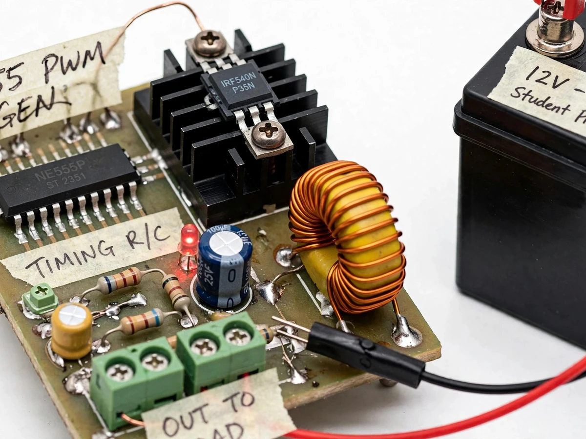
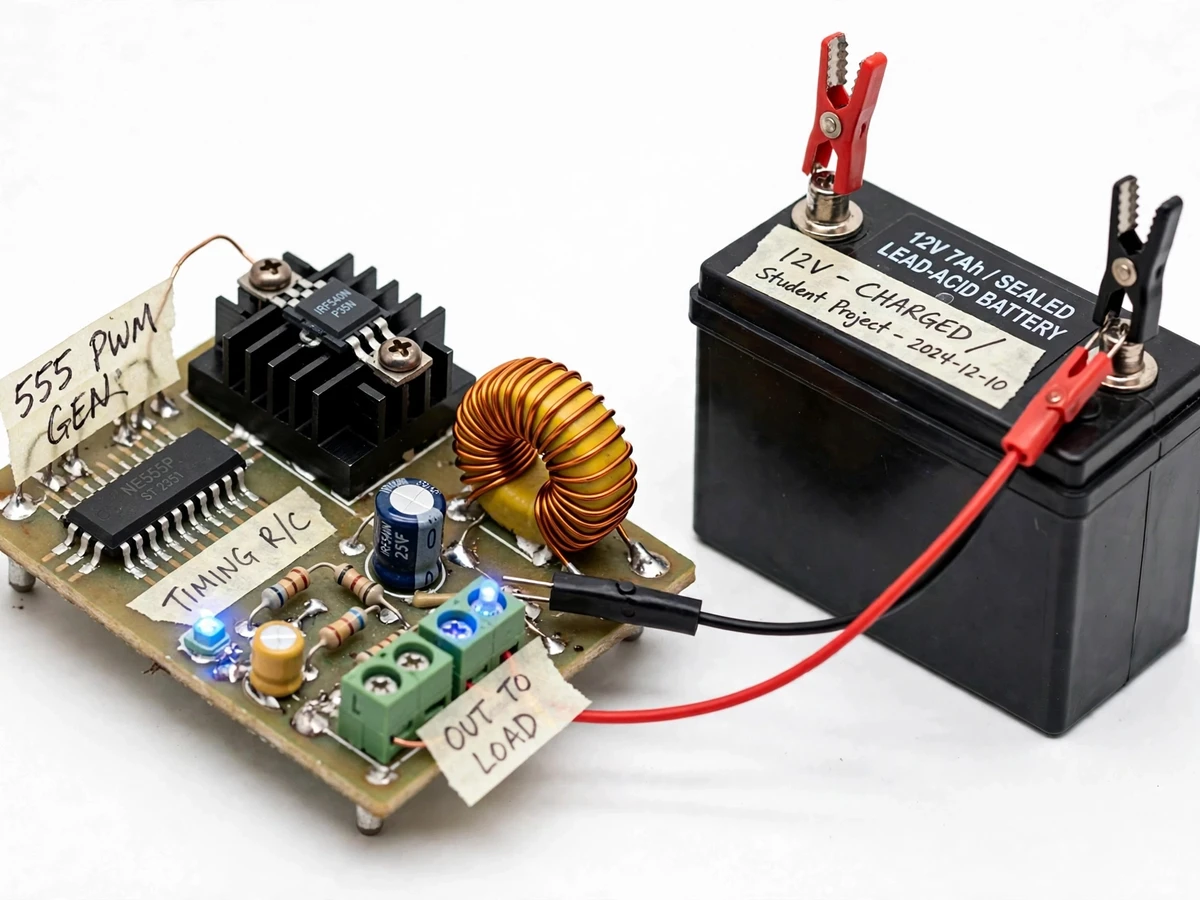
12-15 V DC supply powers the pulse board.
Follow the working sequence
How it works
- A 12-15 V DC supply powers the NE555 wired as an astable multivibrator; R1, R2 and C are chosen with f = 1.44/((R1+2R2)C) to oscillate near 2 kHz, trimmable from 1 to 3 kHz.
- Each 555 output pulse is fed through a gate resistor to the IRF540N; the MOSFET conducts hard for a few tens of microseconds, pulling a sharp current spike from the battery through the series inductor.
- The inductor limits the current rise rate, so the battery experiences a brief high-current pulse instead of a hard short; at pulse end the inductor's flyback energy freewheels through the diode back into the battery, keeping the pulse energy inside the battery loop.
- Repeating this at kilohertz rates, the sharp pulses stress the hardened lead-sulfate crystal layer on the plates, encouraging it to break up and re-dissolve into the electrolyte; the LED blinks once per pulse as a heartbeat.
- Because there are no charging stages, the unit runs in parallel with a normal charger or on its own supply — desulfation conditioning happens independently of the charge cycle.
- The buyer documents results with the included test procedure: the battery is fully charged, then discharged through a known load (for example an automotive lamp), timing how long the terminal voltage stays above 10.8 V; the before/after times give the measured capacity change.
Tech stack:
- NE555 timer IC in astable mode
- IRF540N N-channel MOSFET with heatsink
- Inductor + flyback diode pulse shaping
- Perfboard / custom PCB assembly
- Reverse-polarity blocking diode + series fuse
- 12-15 V DC supply input
- LED pulse-rate indicator
- Digital multimeter + stopwatch test procedure
| Parameter | Value |
|---|---|
| Pulse frequency | 1-3 kHz (design target, trimmable by preset) |
| Pulse generator | NE555 astable; f = 1.44/((R1+2R2)C) |
| Switching device | IRF540N MOSFET, 100 V / 33 A continuous (datasheet) |
| Battery type | 12 V lead-acid: flooded, AGM or gel (design target) |
| Battery capacity range | 7-200 Ah (design target) |
| Supply input | 12-15 V DC |
| Pulse shaping | Series inductor with flyback diode (implemented) |
| Protection | Reverse-polarity blocking diode + series fuse (implemented) |
| Indicator | LED flashing once per pulse (implemented) |
| Conditioning duration | Hours to days of pulse exposure (expected; severity-dependent) |
| Charging function | None — no bulk/absorption/float stages; use alongside a standard charger |
Project features
- [NE555 high-frequency pulse generator] The timer runs in astable mode with frequency set by f = 1.44/((R1+2R2)C), tuned to the 1-3 kHz design target and trimmable with a preset resistor for short, sharp pulses rather than continuous conduction.
- [IRF540N MOSFET switching stage] A genuine IRF540N (100 V, 33 A continuous per its datasheet) switches the pulse current; it sits on a heatsink and is driven through a gate resistor from the 555 output.
- [Inductor-coupled pulse path] A small inductor in series with the battery terminals shapes each pulse — limiting the current rise rate so the battery sees sharp current spikes rather than a sustained short — with a flyback diode protecting the MOSFET from back-EMF.
- [Reverse-polarity protection and fuse] A blocking diode and series fuse guard the board if the battery leads are connected backwards.
- [LED pulse indicator] An LED flashes once per pulse, giving an instant visual confirmation that the pulse train is alive.
- [Works alongside a standard charger] The unit is a conditioner, not a multi-stage charger: it contains no bulk, absorption or float stages, so it complements rather than replaces the buyer's regular charger.
- [Adjustable pulse rate (configurable)] The preset resistor lets the pulse frequency be trimmed across the 1-3 kHz band to match different battery sizes.
What is included
- Working desulfator prototype: pulse board with NE555, IRF540N on heatsink, inductor, screw terminals and croc-clip battery leads
- Circuit diagram with all component values
- 555 timing-network calculations (frequency and duty-cycle derivation)
- Before/after capacity-test procedure document
- Project report PDF (sulfation chemistry, pulse-desulfation theory, circuit design, test method)
- PPT presentation for the final review
- Viva Q&A preparation document
Limitations & prerequisites
- Recovery depends on sulfation severity and plate condition; heavily sulfated, dried-out, or shorted-cell batteries may not respond — no capacity restoration is guaranteed.
- Desulfation takes hours to days of pulse exposure, not minutes; patience and repeated testing are part of the process.
- This unit is a conditioner, not a charger: it has no bulk, absorption or float stages, and the battery still needs normal charging.
- Designed for 12 V lead-acid batteries only (design target); not suitable for lithium-ion, NiMH, or batteries with zero terminal voltage and shorted cells.
- The prototype is a student-built conditioning aid, not a certified battery-servicing instrument; all results are measured by the buyer with the supplied procedure.
- Observe battery-safety practice during use: ventilated area, eye protection, no sparks or flames near battery vents (hydrogen gas).
Frequently Asked Questions
Will this restore a dead battery to full capacity?
Not necessarily. The desulfator can break up hardened lead-sulfate crystals, but only on batteries whose plates are still physically sound. Heavily sulfated, dried-out, or shorted-cell batteries may not respond at all, which is why no capacity-recovery figure is claimed — the included before/after test procedure lets you measure exactly what your battery regained.
Is this the same as a battery charger?
No. A charger moves through bulk, absorption and float voltage stages to refill charge; this unit fires kilohertz current pulses to condition the plates. It has no charging stages, so it complements a normal charger rather than replacing it — the two can run side by side, with the desulfator handling crystal breakup while the charger handles charging.
Which batteries does it work with?
12 V lead-acid batteries of flooded, AGM or gel construction, in the 7-200 Ah design-target range — inverter, automotive and solar batteries, for example. It is not designed for lithium-ion or NiMH packs, and batteries with zero terminal voltage or shorted cells are beyond what pulse conditioning can reach.
Is this project suitable for a final-year project?
Yes — for Electrical and Electronics programs. It demonstrates 555 timer design with real frequency calculations, power MOSFET switching, inductor behaviour, protection circuitry and battery chemistry concepts, plus a documented measurement procedure, which makes it strong material for a final-year build and viva.
What will I receive with the project?
The working desulfator prototype with croc-clip battery leads, the circuit diagram with component values, the 555 timing calculations, the before/after capacity-test procedure, a project report PDF, a PPT for the final review and a viva Q&A document. The unit is built to order, so the hardware is assembled fresh for each buyer.
Components & software requirements
- NE555 timer IC in astable mode
- IRF540N N-channel MOSFET with heatsink
- Inductor + flyback diode pulse shaping
- Perfboard / custom PCB assembly
- Reverse-polarity blocking diode + series fuse
- 12-15 V DC supply input
- LED pulse-rate indicator
- Digital multimeter + stopwatch test procedure
Delivery information
Built-to-order project. Delivery timeline is shared after order confirmation based on current queue.
Support terms
Complete documentation, setup guide, and viva preparation included. Support for setup and explanation provided.
Download free synopsis (PDF)
Enter your name and email — the synopsis PDF downloads immediately. We may send occasional project updates; no spam, unsubscribe anytime.