
More project photos (3)
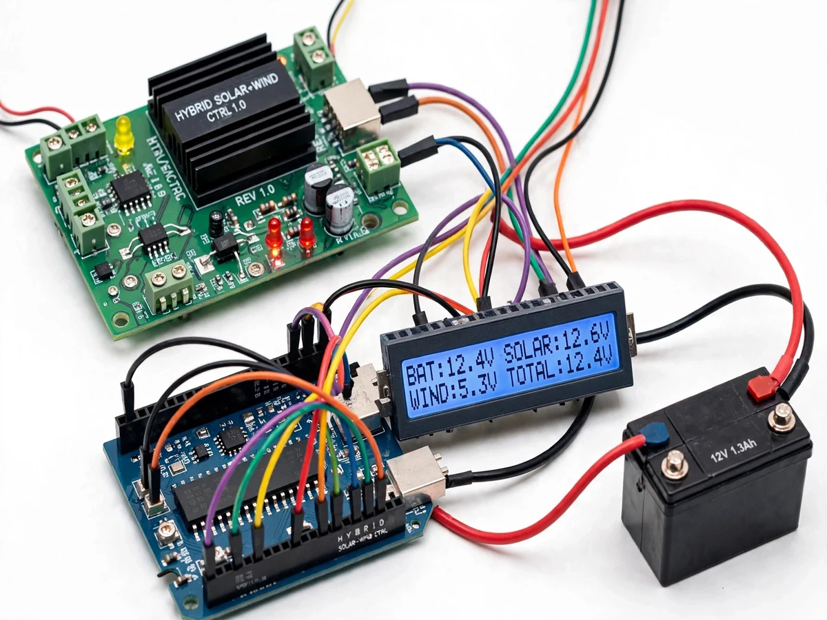
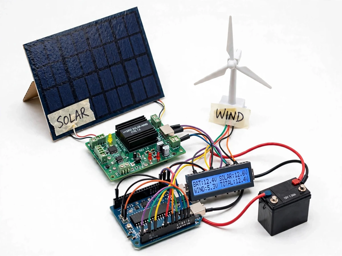
The problem
A single renewable source is an unreliable charger: a solar-only station produces nothing after sunset, and a wind-only station sits idle on calm days, so the battery bank behind either one cycles through deep discharges that shorten its life. Hybrid solar-wind stations address exactly this intermittency — the two sources rarely peak and fade together, so their combined output keeps the bank in a healthier state of charge. But combining them is not just wiring two sources in parallel: the panel and turbine have different voltage-current behavior, the wind side needs overspeed and overvoltage handling, and a lead-acid bank needs a proper bulk/absorption/float profile rather than raw unregulated charging. This project builds that complete small station — panel, miniature turbine, hybrid charge path, monitored 12 V battery bank — as a working prototype that makes renewable integration visible and measurable on the bench.
50 W-class panel feeding the 12 V DC bus through a blocking diode.
Follow the working sequence
How it works
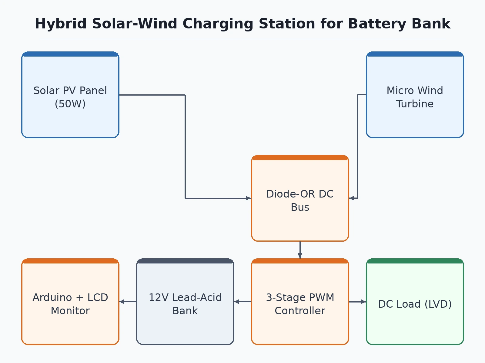
- The solar panel and the wind turbine (through its three-phase rectifier) each produce DC and feed the common bus through blocking diodes that prevent reverse current between sources.
- The INA219 sensor measures the panel's voltage and current while a divider network tracks turbine and battery voltages; the Arduino samples all channels continuously.
- The charge controller applies PWM switching to regulate bus energy into the battery following the three-stage profile: bulk (full current) until the absorption voltage, absorption (constant voltage, tapering current), then float.
- If the turbine voltage exceeds the safe limit — strong gusts with a full battery — the controller switches the dump-load MOSFET on and burns the excess in the resistor bank instead of overcharging the battery.
- The LCD continuously displays panel power, turbine voltage, battery voltage, charging stage and load state, while the same readings are appended to the SD-card log.
- When battery voltage drops below the deep-discharge threshold under load, the relay opens the load output; it reconnects automatically once the bank recovers past the reconnect voltage.
- At any point the student can isolate either source with its switch and observe — on the display and in the log — how the remaining source alone behaves versus the hybrid combination.
Tech stack:
- Arduino Uno/Nano (ATmega328P) for monitoring, charge-stage logic and display
- 50 W-class polycrystalline solar panel (12 V nominal)
- Small permanent-magnet wind turbine with three-phase rectifier (12 V class)
- INA219 current/voltage sensor for panel power measurement
- PWM charge-control stage with dump-load MOSFET and resistive dump bank
- 12 V lead-acid battery bank (sealed, demonstration capacity)
- 16x2 LCD with I2C backpack for live parameter display
- SD-card module for energy logging; relay module for load disconnect
| Parameter | Value |
|---|---|
| Solar input | 50 W-class panel, 12 V nominal (design target; actual output weather-dependent) |
| Wind input | Small 3-phase permanent-magnet turbine, 12 V class with rectifier and dump load |
| Battery bank | 12 V sealed lead-acid bank (demonstration capacity) |
| Charge profile | Three-stage PWM: bulk / absorption / float with temperature-compensated setpoints |
| Monitoring | Panel V/I via INA219, turbine and battery voltage via dividers, Arduino-sampled |
| Display | 16x2 LCD: source powers, battery voltage, charge stage, load state |
| Logging | SD card, voltage and current per source at fixed intervals |
| Load protection | Relay-based low-voltage disconnect with automatic reconnect |
| Output | 12 V DC load terminals (demonstration loads: lamps, small DC motor) |
Project features
- [Dual-source DC bus] A 50 W-class solar panel and a small permanent-magnet wind turbine feed a common 12 V DC bus through blocking diodes, so the stronger source carries the load at any moment without either source back-feeding the other.
- [Three-stage PWM charge control] The charge controller runs bulk, absorption and float stages with temperature-compensated voltage setpoints, giving the lead-acid bank a proper charging profile instead of unregulated trickle charging.
- [Wind overspeed and dump-load handling] When the turbine voltage rises past the safe limit the controller diverts excess energy into a resistive dump load, which both protects the battery and keeps the turbine electrically loaded so it cannot free-spin.
- [Live energy monitoring] An Arduino-based monitor measures panel voltage and current (INA219), turbine voltage and battery voltage, and shows source contributions, charging stage and battery state on an LCD in real time.
- [Low-voltage load disconnect] A relay disconnects the DC load output when battery voltage falls below the deep-discharge threshold and reconnects after recovery, protecting the bank from the deep cycles that shorten lead-acid life.
- [SD-card energy logging] Voltage and current from each source are logged to SD card at fixed intervals, so the report can include genuine charge/discharge curves recorded during the buyer's own test runs.
- [Manual source isolation] Panel and turbine each have an isolation switch, letting the student demonstrate solar-only, wind-only and hybrid charging on the same rig for the report's comparison section.
What is included
- Complete hybrid charging station prototype (panel, turbine, controller, battery bank, enclosure wiring)
- Controller and monitoring firmware (Arduino sketches) with charge-stage and logging logic
- Circuit schematic and wiring diagram (sources, bus, controller, dump load, LVD)
- Bill of materials with part numbers and sourcing notes
- Project report PDF (background, sizing calculations, charge-profile design, buyer-run test procedure and log analysis)
- PPT presentation for final review
- Viva Q&A preparation document (PV characteristics, wind energy basics, lead-acid charging, PWM control)
- Setup and demo guide (site placement, source-isolation demos, recording charge curves)
Advantages
- A 50 W-class solar panel and a small permanent-magnet wind turbine feed a common 12 V DC bus through blocking diodes, so the stronger source carries the load without either source back-feeding the other.
- A three-stage PWM charge controller runs bulk, absorption and float stages with temperature-compensated voltage setpoints for the lead-acid bank.
- Wind overspeed handling diverts excess energy into a resistive dump load, protecting the battery and keeping the turbine electrically loaded so it cannot free-spin.
- An Arduino-based monitor shows panel, turbine and battery parameters live on an LCD, with low-voltage load disconnect protecting the bank from deep discharge.
- Voltage and current from each source are logged to SD card, and isolation switches let the student demonstrate solar-only, wind-only and hybrid charging on the same rig.
Disadvantages
- Energy yield is entirely weather- and site-dependent: a small turbine produces modest power except in genuinely windy spots, and the turbine is a teaching-scale device, not a meaningful household energy source.
- All power figures are design targets from component ratings, not measured site yields; the SD-card logs from the buyer's own test runs are the honest performance record.
- The station is an off-grid 12 V DC prototype with no grid-tie inverter, no mains synchronization and no net-metering capability.
- Lead-acid batteries need ventilation and must not be shorted or overcharged, and night-time and calm-day operation relies on stored battery energy alone, supporting small DC loads, not extended or heavy loads.
Limitations & prerequisites
- Energy yield is entirely weather- and site-dependent: a small turbine produces modest power except in genuinely windy spots, and the report states plainly that the turbine is a teaching-scale device, not a meaningful household energy source.
- All power figures are design targets from component ratings, not measured site yields; the SD-card logs from the buyer's own test runs are the honest performance record, and the report is written around them.
- The station is an off-grid 12 V DC prototype: it has no grid-tie inverter, no mains synchronization and no net-metering capability.
- Lead-acid batteries need ventilation and must not be shorted or overcharged; the controller's setpoints protect against routine overcharge but the bank remains a chemical energy store that demands the handling precautions in the setup guide.
- Turbine mechanical mounting must be rigid and guyed/well-braced; vibration and imbalance at high wind are a mechanical reality of small turbines that the demo placement guide addresses.
- Night-time and calm-day operation relies on stored battery energy alone; the bank's demonstration capacity supports small DC loads, not extended or heavy loads.
Frequently Asked Questions
Is this project suitable for a final-year project?
Yes — it fits Electrical and Electronics programs and demonstrates renewable integration examiners recognize: PV characteristics, small-wind behavior, three-stage battery charging, PWM control and energy monitoring, all visible live on one rig.
What are the two energy sources?
A 50 W-class solar panel and a small permanent-magnet wind turbine (12 V class) with a three-phase rectifier. Each has an isolation switch so solar-only, wind-only and hybrid operation can be demonstrated separately.
How is the battery protected?
The charge controller runs a bulk/absorption/float profile with temperature-compensated setpoints, a dump load absorbs wind excess, and a relay disconnects the load before deep discharge — three independent layers.
How much power does it actually produce?
That depends on sun and wind at your site, and the report is honest about it: component ratings are design targets, and the SD-card logs from your own test runs are the real performance record the report analyzes.
Can it power my home or feed the grid?
No — it is an off-grid 12 V DC teaching prototype for small demonstration loads. Grid-tie needs an inverter, synchronization and utility approval, which are outside this project's scope.
What will I receive with the project?
The complete station prototype, controller/monitoring firmware, schematics and wiring diagrams, bill of materials, project report PDF, PPT, viva Q&A document and the setup/demo guide. Suitable for B.E./B.Tech final-year projects in Electrical and Electronics Engineering.
Components & software requirements
- Arduino Uno/Nano (ATmega328P) for monitoring, charge-stage logic and display
- 50 W-class polycrystalline solar panel (12 V nominal)
- Small permanent-magnet wind turbine with three-phase rectifier (12 V class)
- INA219 current/voltage sensor for panel power measurement
- PWM charge-control stage with dump-load MOSFET and resistive dump bank
- 12 V lead-acid battery bank (sealed, demonstration capacity)
- 16x2 LCD with I2C backpack for live parameter display
- SD-card module for energy logging; relay module for load disconnect
Delivery information
Built-to-order project. Delivery timeline is shared after order confirmation based on current queue.
Support terms
Complete documentation, setup guide, and viva preparation included. Support for setup and explanation provided.
Download free synopsis (PDF)
Enter your name and WhatsApp number — the synopsis PDF downloads immediately. We may send occasional project updates on WhatsApp; no spam.
Optimization of Hybrid PV/Wind Power System for Remote Telecom Station (arXiv:1411.5343)