
More project photos (2)
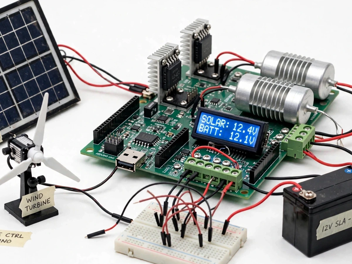
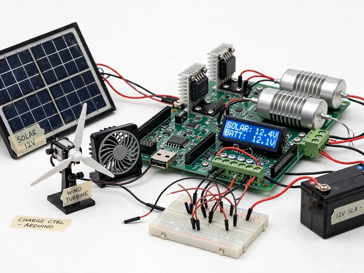
The problem
Most student renewable builds stop at one source: a solar panel wired to a battery through a basic controller, a setup that works in sunlight and stalls. Combining solar and wind fixes the dead hours, but it creates two engineering problems that single-source builds never face. First, the two sources cannot simply be paralleled — the stronger one back-feeds the weaker one — so each source needs isolation through its own blocking diode. Second, specific to wind: a turbine left unloaded when the battery is full spins faster, and small turbines can overspeed, vibrate destructively or overheat their generator windings. Commercial controllers handle this with a dump load, but they are sealed black boxes a student cannot open or explain. This project builds the controller itself: an Arduino-based hybrid charge controller that ORs a solar panel and a 3-blade wind turbine through Schottky diodes, PWM-regulates charging of a 12 V lead-acid battery, switches excess wind power into a dump-load resistor bank when the battery is full, and reports both sources' voltage and current plus battery state on a 16x2 LCD.
3-blade model turbine with DC generator; about 0 to 15 V rectified, up to roughly 10 W in strong wind.
Follow the working sequence
How it works
- The solar panel and the wind turbine each land on their own input terminal block, and each source passes through its own Schottky blocking diode (approximately 0.3–0.6 V forward drop at operating current) onto a shared charge bus — neither source can drive current backward into the other.
- The Arduino samples four analog channels: solar voltage, wind voltage and battery voltage through resistor dividers, plus one ACS712 current module per source leg, so the firmware always knows what each source is producing.
- When battery voltage is below the absorption setpoint (nominally 14.4 V at 25°C, a trimmable design value), the controller drives the charge MOSFET with PWM at approximately 490 Hz default, delivering the combined available current into the 12 V lead-acid battery.
- At the absorption setpoint the firmware switches to voltage-limited charging — the LCD shows steady voltage with tapering current — and then drops to float (nominally 13.6 V), holding the battery without overcharging.
- If the battery is full (float stage, charge current below the tail threshold) while the wind input is still producing, the controller turns on the dump-load MOSFET, routing wind power into the resistor bank; the electrically loaded generator brakes the turbine instead of letting it spin open-circuit.
- After sunset or when both sources fade, charging stops and the DC load terminal runs from the battery until voltage falls to approximately 11.1 V, when the load MOSFET disconnects it; the load reconnects automatically at approximately 12.2 V.
- The 16x2 LCD refreshes approximately every second, cycling through solar V/I, wind V/I, battery voltage and the charge status flags, so the demo shows the whole hybrid behaviour live.
Tech stack:
- Arduino Uno (ATmega328P)
- Schottky diode OR-ing, dual input
- IRFZ44N · PWM charge MOSFET
- Dump-load MOSFET · resistor bank
- ACS712 · dual current sensing
- 16x2 LCD display
- 12 V lead-acid battery
- 3-blade wind turbine · DC generator
| Parameter | Value |
|---|---|
| Solar input | 12 V nominal, up to ~21 V open-circuit (design range) |
| Solar power | Up to ~20 W (design target) |
| Wind input | 3-blade model turbine with DC generator, ~0–15 V rectified (design range) |
| Wind power | Up to ~10 W in strong wind (design target) |
| Battery | 12 V sealed lead-acid, 2.3–7 Ah (design range) |
| Charge regulation | PWM, approximately 490 Hz default, reconfigurable (design value) |
| Absorption / float setpoints | 14.4 V / 13.6 V at 25°C nominal (design values, trimmable in firmware) |
| OR-ing diodes | Schottky, approximately 0.3–0.6 V drop at operating current (datasheet: 0.6 V max at 1 A) |
| Dump load | Finned resistor bank, rated approximately 24 W (design target), MOSFET-switched |
| Dump-load trigger | Battery at float with charge current below tail threshold and wind input present (design logic) |
| Current sensing | 2 × ACS712 modules, ±5 A variant (datasheet range) |
| LVD disconnect / reconnect | Approximately 11.1 V / 12.2 V (configurable in firmware) |
| Display | 16x2 LCD, refreshed approximately 1 Hz |
Project features
- [Dual-source hybrid charging] A 12 V solar panel and a 3-blade wind turbine feed a common charge bus through separate Schottky OR-ing diodes, so the controller charges from whichever source is producing — and from both together when sun and wind coincide — with no back-feeding between sources.
- [Wind dump-load overspeed protection] When the battery is full and the wind turbine is still generating, a second MOSFET switches the wind side into a finned resistor dump-load bank; the loaded generator slows down electrically, so the turbine never spins open-circuit at overspeed.
- [PWM charge regulation] An Arduino-driven power MOSFET regulates battery charging with PWM; the absorption (nominally 14.4 V at 25°C) and float (nominally 13.6 V at 25°C) setpoints are named firmware constants the student trims during their own calibration.
- [Dual-source telemetry on 16x2 LCD] The blue-backlit display cycles through solar voltage and current, wind voltage and current, battery voltage, and the active charge status (charging, absorption, float, dump-load active), refreshing approximately once per second.
- [Per-source current sensing] An ACS712 Hall-effect module on each source leg measures what the solar panel and the wind turbine actually contribute, giving the student real data for the solar-vs-wind energy comparison experiment in the report.
- [Load low-voltage disconnect] The DC load output disconnects at approximately 11.1 V and reconnects at approximately 12.2 V, protecting the battery from deep discharge when the load runs on stored energy.
- [Configurable setpoints, documented upgrade path] Charge voltages, the dump-load trigger point and LVD thresholds are editable constants in the firmware; the report documents optional upgrades such as MPPT on the solar leg, a larger turbine-generator, and SD-card data logging.
What is included
- Working solar-wind hybrid charge controller prototype (controller board, charge and dump-load MOSFET stages, finned dump-load resistor bank, LCD, current sensors)
- Small 12 V solar panel and 3-blade wind turbine model with DC generator
- 12 V sealed lead-acid battery
- Arduino firmware source code with commented setpoint constants
- Circuit and wiring documentation (dual inputs, diode OR-ing, dump-load stage, LVD output)
- Buyer-run calibration procedure (voltage-divider trim, current-sensor offset, setpoint trim)
- Solar-vs-wind energy comparison test procedure for the report
- Project report PDF (theory, design calculations, build procedure, testing methodology)
- PPT presentation for final review
- Viva Q&A preparation document (diode OR-ing, PWM charging, dump loads, lead-acid charge stages)
Limitations & prerequisites
- A scaled demonstration system (~20 W solar class, ~10 W wind class): it demonstrates hybrid charge-control principles, not house-scale power.
- Wind output is inherently variable — on still days the turbine contributes nothing, so the report's energy comparison must be logged over several days, never from a single reading.
- The approximately 0.3–0.6 V Schottky drop costs a small fraction of input power; the loss is quantified in the report's energy budget, not hidden.
- The dump-load resistor bank dissipates excess wind energy as heat and needs ventilation — it gets hot during sustained dumping.
- The prototype is an indoor academic build, not weatherproof and not grid-certified; it is not rated for permanent outdoor installation.
- Absorption and float setpoints are design values the student trims during their own calibration; no charging efficiency is claimed as measured without the buyer-run test procedure.
- A small DC-generator model turbine is noisier and less efficient than a real wind turbine — the report states this honestly.
Frequently Asked Questions
Is this project suitable for a final-year project?
Yes — for Electrical and Electronics/E&TC programs. It combines power electronics (PWM switching, MOSFET stages), embedded firmware (ADC sensing, control logic), and renewable-energy engineering (source management, lead-acid charging, wind overspeed protection) in one working system. The solar-vs-wind energy comparison and the dump-load protection stage give the student measurable, explainable results for the report and the live demo.
How does the dump load protect the wind turbine?
A small wind turbine with nowhere to send its power spins faster as the wind pushes it, and at overspeed it can vibrate destructively or overheat its generator. When the battery is full, the controller switches the wind output into the resistor dump-load bank, which electrically loads the generator and brakes the rotor — the same diversion-load principle real small wind systems use, implemented in firmware.
Why Schottky diodes instead of regular diodes?
A regular silicon diode drops about 0.7 V; in a 12 V system that is wasted power and lost charging headroom. A Schottky diode drops only about 0.3–0.6 V at operating current (datasheet: 0.6 V maximum at 1 A), so more of each source's voltage reaches the battery. Each source gets its own diode so the stronger source can never back-feed the weaker one.
How is this different from a solar-only charge controller?
They solve different problems. A solar-only controller manages one source through its charge stages. This build manages two: it adds diode OR-ing so the sources cannot back-feed each other, per-source current sensing to compare each source's real contribution, and a wind dump load for overspeed protection — a failure mode that solar panels simply do not have.
Why can't I just wire the panel and turbine in parallel?
Because the higher-voltage source would push current backward into the lower-voltage one — at night a battery would even discharge into the panel. Each source's own Schottky diode lets current flow only toward the battery, which is what makes the hybrid input work.
How do I prove it works during my demo?
The build ships with two buyer-run procedures: a calibration procedure for the voltage and current channels, and an energy-comparison test where you log solar V/I, wind V/I and battery voltage from the LCD over a charge cycle, then demonstrate the dump-load stage by letting the battery reach float while the fan drives the turbine. Your report presents your own measured readings — never pre-invented numbers.
Components & software requirements
- Arduino Uno (ATmega328P)
- Schottky diode OR-ing, dual input
- IRFZ44N · PWM charge MOSFET
- Dump-load MOSFET · resistor bank
- ACS712 · dual current sensing
- 16x2 LCD display
- 12 V lead-acid battery
- 3-blade wind turbine · DC generator
Delivery information
Built-to-order project. Delivery timeline is shared after order confirmation based on current queue.
Support terms
Complete documentation, setup guide, and viva preparation included. Support for setup and explanation provided.
Download free synopsis (PDF)
Enter your name and WhatsApp number — the synopsis PDF downloads immediately. We may send occasional project updates on WhatsApp; no spam.