
More project photos (2)
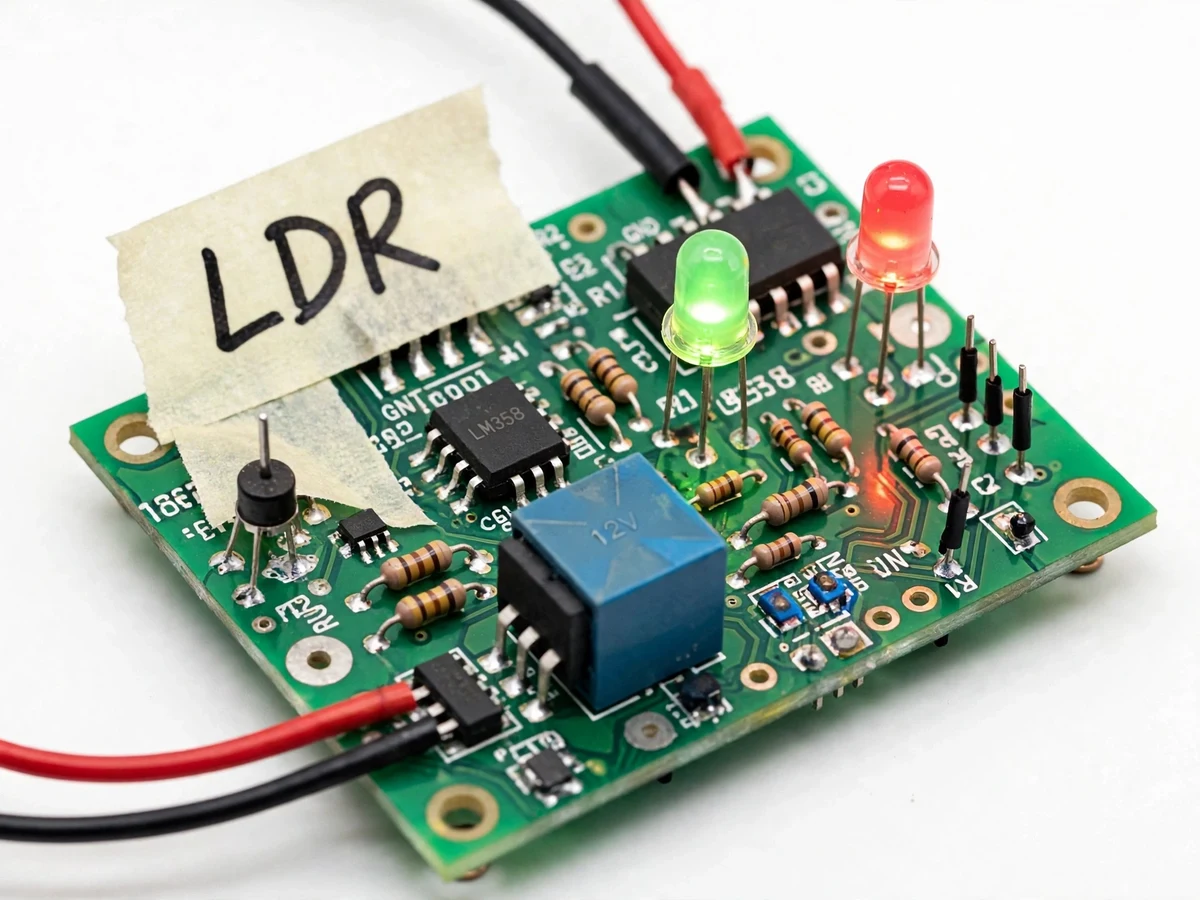

The problem
The Automatic Emergency Light Project with LDR Auto-On, Battery Backup and Solar Charging keeps a 12 V LED panel lit through power cuts. When the mains supply fails, a 12 V relay-based failover circuit switches the lamp to a rechargeable battery pack in a fraction of a second, and an LDR sensor gates the lamp so it only lights when the room is dark. A 6 V solar panel recharges the battery in daylight through a charge-control stage with overcharge cut-off. It answers a familiar problem: rooms without inverters go dark during load shedding, and torches run flat because nobody charges them. It combines three lab-familiar ideas — LDR sensing with a comparator, relay changeover switching, and small-scale solar charging — into one prototype. The lamp is demonstrated live by unplugging the mains or covering the LDR, making the sensing, switching and charging visible in one bench test.
230 VAC feed holds the failover relay energised while the supply is healthy.
How it works
End to end, the circuit has three jobs: sense the mains, sense the light, and keep the battery charged. A 230 VAC mains feed runs through a small step-down transformer and rectifier to produce a DC sense voltage that holds the 12 V SPDT relay energized while the supply is healthy. The moment the mains fails, the relay drops out and its changeover contacts route the battery pack to the 12 V LED panel — the lamp switches over in a fraction of a second. In series with that path, an LDR stage decides whether the lamp should actually light: a GL5528 photoresistor in a voltage divider feeds an LM358 comparator whose trimmer-set threshold defines darkness, and only below that threshold does the lamp energize. Meanwhile a 6 V, 3 W solar panel feeds a charge-control stage that tops the battery up in daylight with overcharge cut-off near 13.8 V. Red and green indicators report charging and system state continuously.
- The 230 VAC mains input is stepped down and rectified to a DC sense voltage that keeps the 12 V SPDT relay coil energized; while the mains is healthy the lamp path stays on the mains side.
- When the mains supply fails, the relay drops out and its changeover contacts route the rechargeable 12 V battery pack to the LED panel driver — failover completes in a fraction of a second (design target).
- A GL5528 LDR in a voltage divider feeds one input of the LM358 comparator; a trimmer potentiometer sets the reference for the other input, defining the exact darkness threshold.
- Only when ambient light falls below the threshold does the comparator enable the lamp — mains failure and darkness must coincide (AND logic), so daylight outages never drain the battery.
- A 6 V, 3 W polycrystalline solar panel feeds the charge-control stage during daylight; charging current flows into the battery and the red indicator shows charging.
- The charge comparator cuts the charge path near 13.8 V (design target, calibrated during the build) and the green indicator confirms the charged state; the ~0.3 V hysteresis band prevents flicker at the cut-off.
- When the mains supply returns, the relay re-energizes, the lamp goes back to the mains path, and solar charging resumes — the whole cycle is automatic.
Tech stack:
- LM358 dual comparator
- GL5528 LDR photoresistor
- 12 V SPDT failover relay
- 12 V · 6 W LED panel
- 12 V rechargeable battery pack
- 6 V · 3 W solar panel
- Charge controller stage
- Trimmer-set thresholds
| Parameter | Value |
|---|---|
| Lamp | 12 V DC LED panel, 6 W (datasheet) |
| Battery | 12 V nominal rechargeable pack, approximately 5–7 Ah (expected) |
| Solar input | 6 V polycrystalline panel, 3 W (datasheet) |
| Light sensor | GL5528 LDR: ~8–20 kΩ at 10 lux, ~1 MΩ in darkness (datasheet) |
| Failover relay | 12 V SPDT, contacts 10 A / 250 VAC (datasheet) |
| Failover time | Fraction of a second — relay drop-out (design target) |
| Backup time | Approximately 4–6 hours on a full charge (expected, load-dependent) |
| Charge cut-off | ~13.8 V overcharge cut-off (design target, calibrated during build) |
| Sensitivity | Adjustable via trimmer potentiometer |
| Indicators | Red = charging, green = battery/mains OK |
Project features
The four capabilities that define this build are darkness-gated auto-on, mains-failover switching, solar charging and status indication. Darkness-gated auto-on uses a GL5528 LDR feeding an LM358 comparator with a trimmer-set threshold, so the lamp only turns on below the light level you calibrate — and a hysteresis band keeps the lamp from flickering at the trip point around dusk. Mains-failover switching uses a 12 V SPDT relay that drops the lamp to battery power in a fraction of a second when the mains supply fails and restores it when the supply returns, without any switch being touched. Solar charging comes from a 6 V, 3 W polycrystalline panel feeding a charge-control stage with overcharge cut-off, so the battery recovers itself in daylight. Status indication is handled by red and green LEDs showing charging and system state, giving you visible feedback on every state the circuit can be in.
- [LDR auto-on with adjustable threshold] A GL5528 photoresistor in a voltage divider feeds an LM358 comparator; a trimmer sets the darkness threshold, and a ~0.3 V hysteresis band on the comparator stops the lamp flickering when ambient light hovers at the trip point around dusk.
- [Mains-failover relay switching] A 12 V SPDT relay (JQC-3F class, 10 A / 250 VAC contacts, datasheet) monitors the mains; when the supply fails it drops the lamp to battery power in a fraction of a second, and restores the mains path when the supply returns.
- [Darkness-gated power logic] The lamp energizes only when two conditions coincide — the mains has failed AND ambient light is below threshold. The principle, in one line: the LDR only switches the lamp when darkness and mains failure coincide — an AND gate built in hardware, so daylight power cuts never drain the battery.
- [Solar charging input] A 6 V, 3 W polycrystalline panel (datasheet) charges the battery through a charge-control stage with overcharge cut-off set near 13.8 V (design target, calibrated during the build).
- [Rechargeable battery backup] A nominal 12 V battery pack keeps the 6 W LED panel lit for approximately 4–6 hours on a full charge (expected, load-dependent).
- [Charge and status indicators] Red LED shows charging, green LED shows battery/mains status. Builder note from the prototype wiring: the charge comparator uses a ~0.3 V hysteresis band so the green indicator stays on until the battery genuinely crosses the full-charge threshold instead of flickering at the trip point.
- [Live bench demonstration] Unplug the mains to show failover, or cover the LDR to show darkness gating — every behaviour in this build is demonstrable in one bench test with no extra instruments.
What is included
- Working emergency-light prototype (control board, battery pack, solar panel, LED panel)
- Circuit diagram and wiring documentation
- Component list with datasheet references
- Calibration procedure for the LDR threshold and charge cut-off
- Project report PDF (background, circuit theory, methodology, results)
- PPT presentation for final review
- Viva Q&A preparation document
Limitations & prerequisites
- Backup time of approximately 4–6 hours is an estimate, not a measured guarantee — it varies with battery age, sunlight and the actual lamp load.
- The 6 V, 3 W panel is a trickle charger; a full day of good sunlight is needed to recover a deeply discharged battery.
- This lights one 12 V lamp — it is not a household inverter and cannot run room circuits or appliances.
- The LDR threshold must be re-tuned if the unit is installed near another light source or behind a tinted window.
- The battery needs periodic charging even when unused, or it will self-discharge below the usable level.
- Relay changeover has a millisecond dropout gap; it is a lamp circuit, not an uninterruptible supply for sensitive electronics.
- The prototype is not a certified safety device; mains-side wiring follows only the documented build procedure.
Frequently Asked Questions
How does the LDR auto-on actually work?
A GL5528 photoresistor forms a voltage divider whose output tracks ambient light, and an LM358 comparator compares it against a trimmer-set reference. When light falls below the calibrated threshold, the comparator enables the lamp driver. A ~0.3 V hysteresis band keeps the lamp from flickering when dusk light hovers at the trip point, and the threshold itself is set with the trimmer during calibration.
What happens the moment the power fails?
The 12 V SPDT relay, which stays energized while the mains supply is healthy, drops out and its changeover contacts route the battery pack to the LED panel — the switch-over completes in a fraction of a second (design target). But the lamp only lights if the LDR stage also reports darkness: mains failure and darkness must coincide. When the supply returns, the relay re-energizes and the lamp goes back to the mains path automatically.
How long does the battery last, and how does the solar panel recharge it?
A fully charged 12 V pack runs the 6 W LED panel for approximately 4–6 hours (expected, load-dependent) — an estimate, not a measured guarantee, since battery age and sunlight vary. The 6 V, 3 W solar panel trickle-charges the battery through a charge-control stage during daylight, with overcharge cut-off near 13.8 V (design target) and red/green indicators showing the charge state.
Is this project suitable for a final-year project?
Yes — it fits Electrical engineering programs well, and Electronics students can also take it up for the sensing and comparator design. It demonstrates LDR-based light sensing, op-amp comparator circuits, relay-based changeover switching and small-scale solar charging in one working prototype, and every behaviour is demonstrable live by unplugging the mains or covering the LDR.
Can the project be customized?
Yes — realistic options include a larger solar panel for faster charging, additional LED lamps on the same control board, a battery-level indicator, or an optional GSM/SMS alert on mains failure. Such additions are developed as customizations beyond the base build, not part of the standard prototype.
What will I need for the live demonstration?
Just a 230 VAC mains socket and daylight (or a bright lamp) for the solar side; the battery ships charged. Unplug the mains to demonstrate failover, or cover the LDR with your hand to demonstrate darkness gating. No extra instruments are needed — the red and green indicators narrate the circuit state.
Components & software requirements
- LM358 dual comparator
- GL5528 LDR photoresistor
- 12 V SPDT failover relay
- 12 V · 6 W LED panel
- 12 V rechargeable battery pack
- 6 V · 3 W solar panel
- Charge controller stage
- Trimmer-set thresholds
Delivery information
Built-to-order project. Delivery timeline is shared after order confirmation based on current queue.
Support terms
Complete documentation, setup guide, and viva preparation included. Support for setup and explanation provided.
Download free synopsis (PDF)
Enter your name and WhatsApp number — the synopsis PDF downloads immediately. We may send occasional project updates on WhatsApp; no spam.