
More project photos (2)
The problem
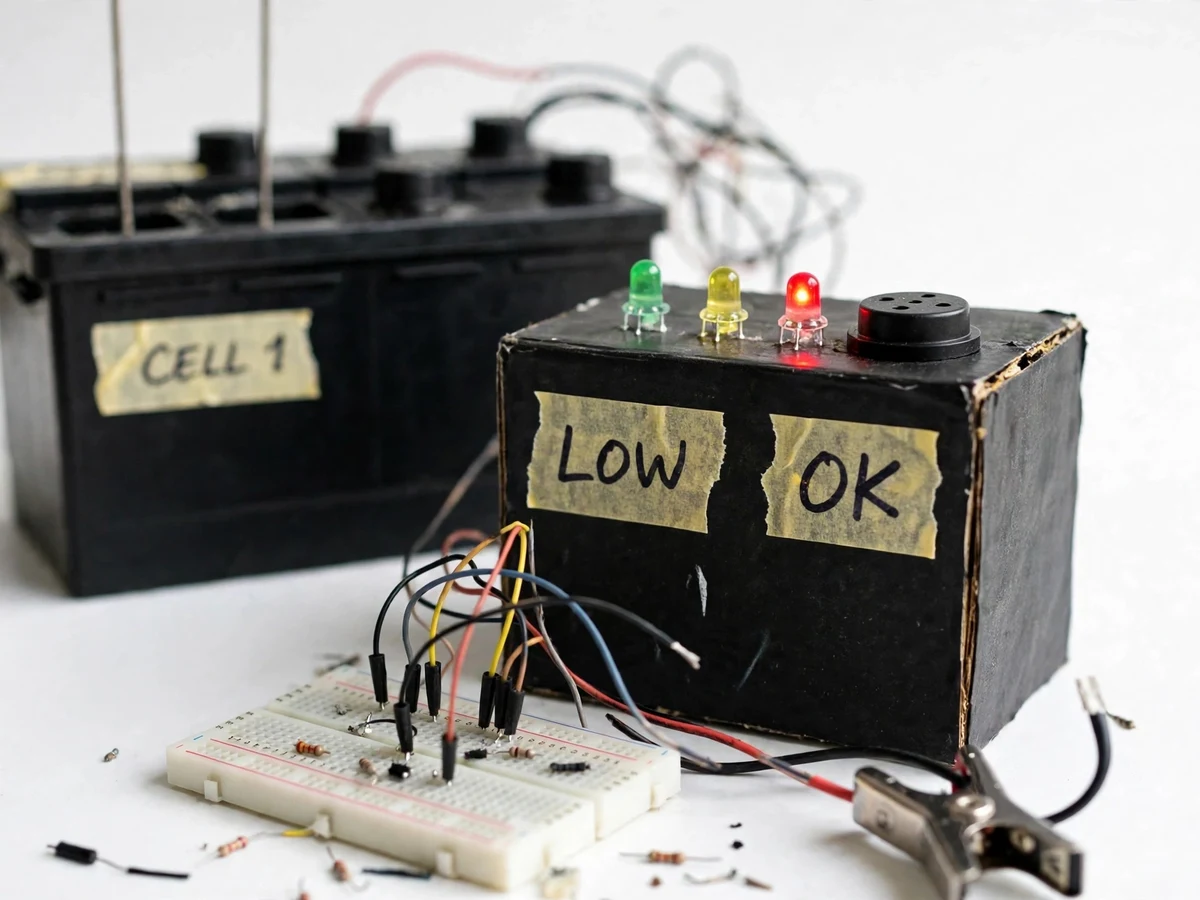
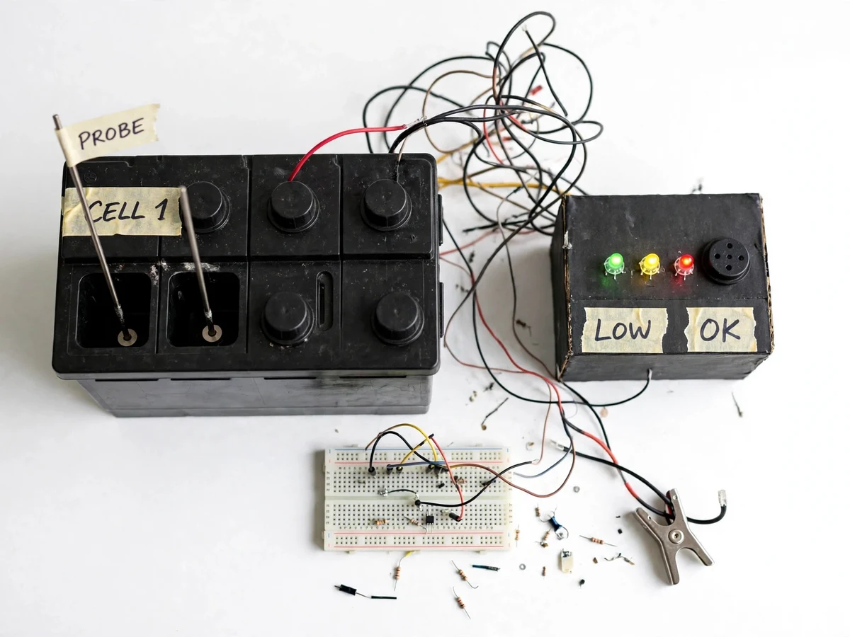
Most Indian homes run on a flooded lead-acid inverter battery, and that battery quietly loses water every time it charges. Charging splits some electrolyte water into hydrogen and oxygen gas, so the level in each of the battery's six cells falls a little with every charge cycle, even without a leak. Once the level drops below the top of the plates, the exposed plate area dries out, sulphates, and never recovers its full capacity. Owners usually notice only when backup time has shrunk, because checking six cell caps with a torch is tedious and easy to postpone. This DIY battery water level indicator for inverter batteries fixes that neglect: stainless-steel probes sit inside a cell, a comparator watches whether electrolyte touches the probe tips, and a three-LED panel plus a buzzer shows the level at a glance. The build needs no microcontroller and no display — just probes, a comparator, LEDs and a buzzer — a clear, hands-on Electrical project.
12 V flooded lead-acid inverter battery, six cells.
Follow the working sequence
How it works
Two stainless-steel probes hang inside one battery cell at two heights: a long probe reaching the full-level mark and a shorter probe ending at the minimum-level line, with a common reference probe reaching the bottom. Electrolyte is conductive, so when the liquid covers a probe tip, a tiny current flows from that probe through the electrolyte to the reference probe; when the level falls below a tip, that path breaks. Each probe feeds one channel of an LM358 comparator, which compares the probe voltage against a fixed reference and switches its output high or low. The comparator outputs drive three LEDs — green while the full probe is covered, yellow while only the middle probe is covered, red when neither is — and the red channel also switches on the buzzer through a transistor. The result is a live, at-a-glance level reading that updates the moment the electrolyte moves.
- Two probe rods and a reference rod are fixed through the cap of one battery cell at the full-level and minimum-level heights.
- Electrolyte touching a probe tip completes a low-current path to the reference probe; a dry tip breaks the path.
- Each probe connects to one LM358 comparator channel, which compares the probe voltage with a preset reference voltage.
- The comparator outputs switch the green, yellow and red LEDs to show full, medium or low level.
- When the level falls below the minimum probe, the red channel turns on the 5 V buzzer through a BC547 transistor.
- A test switch shorts the probe inputs briefly so the user can check all LEDs and the buzzer without changing the water level.
Tech stack:
- 12 V flooded lead-acid inverter battery
- Stainless-steel probe sensors
- LM358 comparator IC
- BC547 NPN transistor switching
- 3-LED level display · 5 V buzzer
- 9 V regulated power supply
- Breadboard · perfboard assembly
- Digital multimeter · hydrometer
| Parameter | Value |
|---|---|
| Battery type | 12 V flooded lead-acid inverter battery (6 cells × 2 V nominal per cell — datasheet value) |
| Cells monitored | 1 cell in the base build; expandable to 6 cells (design value) |
| Level sensing | 2 stainless-steel probes per monitored cell plus 1 reference probe (design value) |
| Probe length | Approximately 100 mm stainless-steel rods (design value) |
| Low probe position | Approximately 10 mm below the full-level mark (design value) |
| Level indication | 3 LEDs — green (full), yellow (medium), red (low) |
| Low-level alert | 5 V active buzzer (datasheet value) |
| Sensing current | Less than 1 mA per probe (design target) |
| Indicator supply | 9 V battery supply (design value) |
| Response time | LED changes within approximately 1 second of a level change (design target) |
| Enclosure | Handmade indicator panel box, approximately 120 mm × 80 mm × 50 mm (design value) |
| Operating temperature | Approximately 0–45 °C indoor use (design target) |
Project features
The strongest parts of this build are its per-cell probe sensing, its three-step LED indication, and its low-level buzzer alert. Two stainless-steel probes sit at different heights inside a monitored cell, so the circuit can tell full, medium and low apart instead of giving a single yes-or-no reading. A green LED means the electrolyte is at the full mark, yellow means it has fallen to the middle probe, and red plus the buzzer means the level has reached the minimum line and needs distilled water. Because sensing uses the electrolyte's own conductivity and a comparator with a tiny sensing current, the circuit stays simple, cheap and easy to explain in a viva. A manual test switch lets the user prove the LEDs and buzzer work without waiting for the level to fall, and the whole indicator runs from a small 9 V supply so it keeps working during a power cut.
- [Per-cell probe sensing] Two stainless-steel probe rods sit at the full-level and minimum-level heights inside a battery cell, so the circuit reads the actual electrolyte level instead of guessing it from voltage or backup time.
- [Three-step LED level display] Green, yellow and red LEDs show full, medium and low level at a glance, so anyone in the house can read the battery's water status without opening a cell cap.
- [Low-level buzzer alert] A 5 V buzzer sounds when the electrolyte falls to the minimum probe, giving an audible warning before the plates are exposed.
- [Comparator-based sensing, no microcontroller] An LM358 comparator compares each probe voltage against a fixed reference, so the whole indicator works with basic analogue electronics and no code.
- [Manual test switch] A push switch simulates a low level on demand, letting the user verify every LED and the buzzer in seconds during a demonstration.
- [Low sensing current protects the probes] Each probe carries less than 1 mA (design target), which limits electrolysis at the probe tips and slows corrosion of the stainless-steel rods.
- [Expandable to all six cells] The base build monitors 1 cell; the same probe-and-comparator channel repeats for the remaining cells, so the panel can grow to full-battery monitoring.
What is included
- Working water level indicator prototype (probe assembly + LED/buzzer panel + comparator circuit) demonstrated on a flooded lead-acid battery
- Circuit diagram and wiring documentation with component list
- Probe fitting and calibration guide for the monitored cell
- Project report PDF (background, electrochemistry, circuit working, methodology, results)
- Project abstract PDF for submission
- PPT presentation for final review
- Viva Q&A preparation document (lead-acid chemistry, comparator working, probe corrosion, safety)
Limitations & prerequisites
- Monitors electrolyte level only; it does not measure charge, voltage or specific gravity — a hydrometer is still needed for a health check.
- The base build watches 1 cell and assumes the other cells behave similarly; full 6-cell monitoring is an add-on, not included.
- Probe tips need periodic cleaning because acid vapour can dull the contacts over months of use (expected).
- Works only with flooded lead-acid batteries; sealed or maintenance-free (SMF/VRLA) batteries have no accessible cells.
- The prototype is an academic build, not a certified battery-safety device; acid handling and ventilation rules still apply.
- If the 9 V indicator supply goes flat, the LEDs and buzzer stop working, so the supply must be checked during routine maintenance.
Frequently Asked Questions
Is this project suitable for a final-year project?
Yes — for Electrical Engineering and Electronics & Telecommunication students, this project demonstrates analogue sensing, comparator circuits, electrochemistry and practical battery maintenance in one working prototype that solves a real household problem and gives the viva discussion genuine technical depth. It is simple enough to build and explain confidently, yet rich enough to discuss in depth.
Which battery types does it work with?
It works with flooded lead-acid inverter batteries, the type with removable cell caps found in most Indian homes, because the probes need open access to the liquid electrolyte inside each cell, and the demo build uses a standard 12 V inverter battery with six cells. Each cell holds dilute sulphuric acid electrolyte. Sealed, maintenance-free or lithium batteries have no accessible liquid level, so the design does not suit them.
Why must only distilled water be used for top-up?
Only distilled water should be used because tap water carries dissolved minerals such as calcium, magnesium and iron salts that deposit on the plates and separators, raise self-discharge and permanently reduce the battery's capacity over time, while distilled water replaces exactly the pure water lost to electrolysis during charging. The report explains this chemistry so the choice can be defended in a viva.
Will the probes corrode inside the battery acid?
Stainless-steel probes resist the dilute sulphuric acid far better than mild steel or copper, and the sensing current is kept below 1 mA (design target) so electrolysis at the tips stays minimal and the probe tips stay clean and conductive through repeated level checks in normal use. Even so, the tips need occasional cleaning, and the report documents probe inspection as part of routine maintenance.
Does it need a microcontroller or internet?
No — the entire indicator is analogue, built from probes, an LM358 comparator, transistors, LEDs and a buzzer, with no code, no microcontroller and no internet connection of any kind, so it works during a power cut and needs nothing beyond its 9 V supply. That keeps the cost low, the circuit easy to debug, and the working easy to explain; a microcontroller display version is listed as future scope.
Can it monitor all six cells instead of one?
Yes — the same probe-and-comparator channel repeats for each cell, so the panel can grow to six sets of LEDs with one shared buzzer, covering the whole battery instead of a single cell, and the report explains the expansion wiring for the remaining five cells. The base build monitors 1 cell to keep the circuit simple and the cost low.
Components & software requirements
- 12 V flooded lead-acid inverter battery
- Stainless-steel probe sensors
- LM358 comparator IC
- BC547 NPN transistor switching
- 3-LED level display · 5 V buzzer
- 9 V regulated power supply
- Breadboard · perfboard assembly
- Digital multimeter · hydrometer
Delivery information
Built-to-order project. Delivery timeline is shared after order confirmation based on current queue.
Support terms
Complete documentation, setup guide, and viva preparation included. Support for setup and explanation provided.
Download free synopsis (PDF)
Enter your name and WhatsApp number — the synopsis PDF downloads immediately. We may send occasional project updates on WhatsApp; no spam.