
More project photos (2)
The problem
Most small inverters output a two-level square-ish waveform: cheap to build, but rich in harmonics that heat up motors, buzz in audio equipment and distort measurements. Multilevel inverters solve this by stacking smaller voltage steps into a staircase that approximates a sine wave, cutting harmonic distortion and switching stress. The cascaded H-bridge is the textbook topology for the idea — series-connected H-bridge cells, each fed by its own isolated DC source, whose outputs add up step by step. This project builds a single-phase five-level version as a low-voltage lab prototype: two MOSFET H-bridge modules, two isolated 12 V DC supplies, opto-isolated gate drivers and an Arduino generating the switching sequence. A CRO probe point lets the five-step staircase be captured and compared against a two-level waveform. It is a teaching prototype for power-electronics concepts — topology, isolation, dead time and harmonic content — not a mains appliance.
How it works
- Two isolated 12 V DC supplies power the two H-bridge modules independently.
- The Arduino computes gate timing from its switching-angle table and outputs eight logic signals.
- Opto-isolated drivers translate these into gate drive for the eight MOSFETs, with dead time between complementary switches.
- Each bridge contributes plus Vdc, zero or minus Vdc; the series connection sums them into the five-level staircase.
- The staircase feeds a resistive demo load (lamp); an optional LC filter smooths it toward a sine.
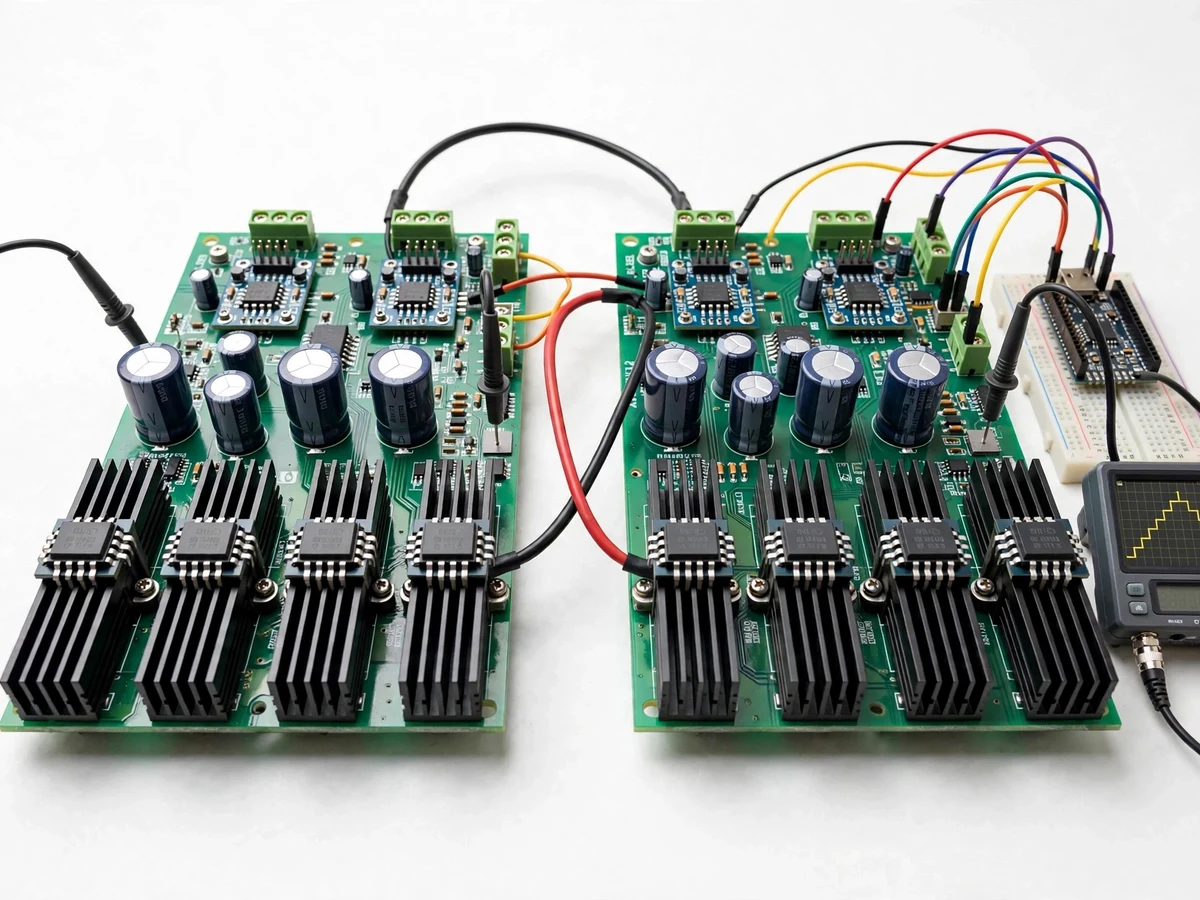
- CRO test points let the waveform be captured so the step levels can be observed and compared against two-level output.
Tech stack:
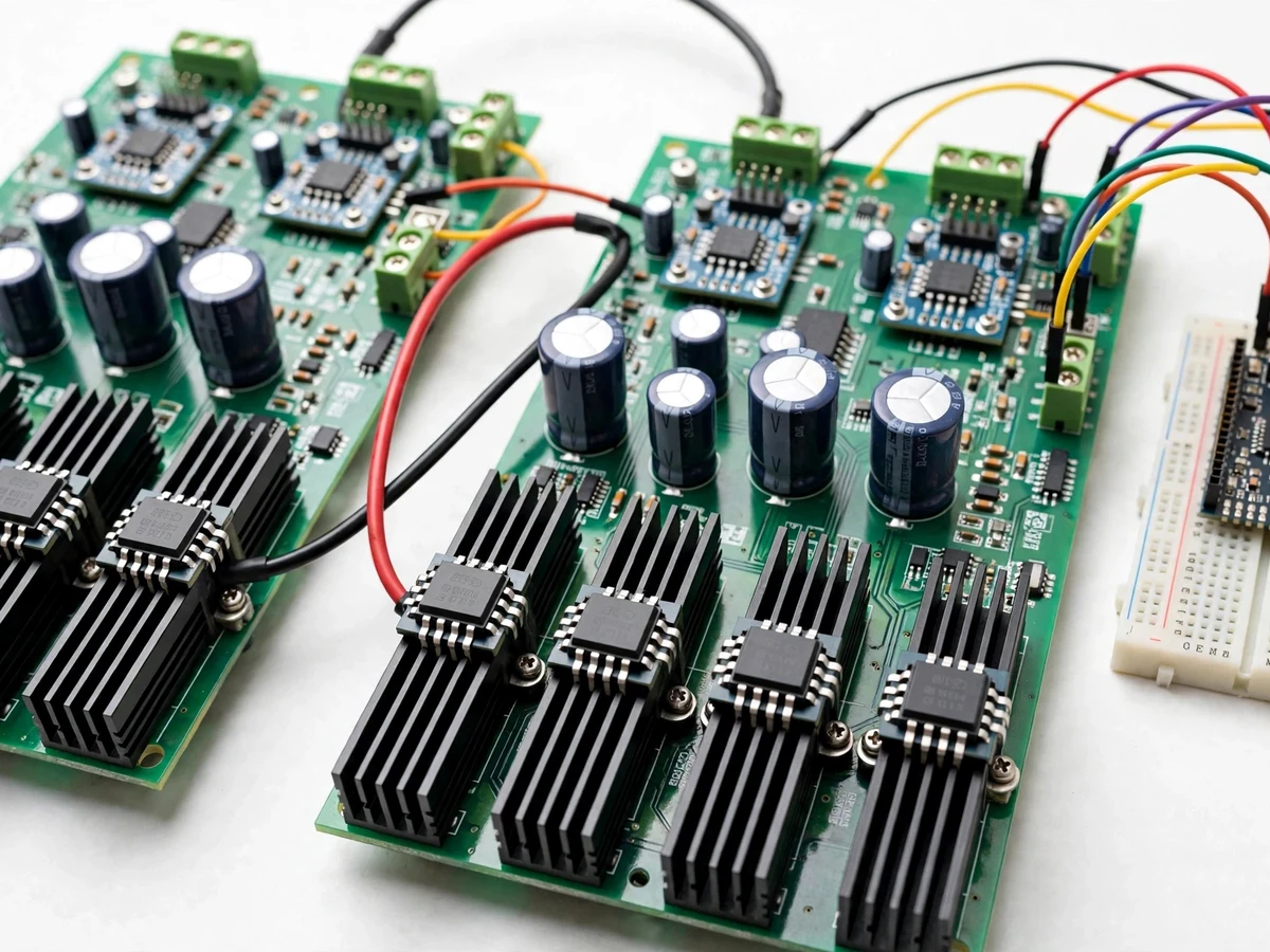
- Power MOSFETs on aluminium heatsinks (two H-bridge modules)
- Opto-isolated gate driver ICs
- Arduino Uno/Nano (switching sequence generation)
- Two isolated 12 V transformer-rectifier DC supplies
- DC-link electrolytic capacitors
- Resistive demo load (lamp) with optional LC filter
- CRO/DSO for waveform verification
| Parameter | Value |
|---|---|
| Topology | Single-phase cascaded H-bridge, 5 levels |
| Switches | 8x power MOSFETs with heatsinks |
| DC buses | 2x isolated 12 V DC (transformer-rectifier), fused |
| Output | Five-level staircase, approx. 24 V peak (design) |
| Fundamental frequency | 50 Hz (firmware-set) |
| Gate drive | Opto-isolated drivers with programmed dead time |
| Load | Resistive demo lamp; optional LC filter |
| Verification | CRO test points — THD observed by buyer, not pre-claimed |
Project features
- [Two cascaded H-bridge modules] Eight power MOSFETs on heatsinks form two full bridges whose outputs add in series to synthesise the five-level staircase.
- [Isolated DC sources] Two separate transformer-rectifier 12 V supplies give each bridge its own floating DC bus — the key isolation requirement of the topology, demonstrated physically.
- [Opto-isolated gate drivers] Driver ICs isolate the Arduino's 5 V logic from the power stage, a standard power-electronics safety practice.
- [Arduino switching sequence] The Arduino generates the eight gate signals with programmed dead time; the switching-angle table is editable in firmware.
- [Five-level staircase output] Plus 2Vdc, plus Vdc, zero, minus Vdc and minus 2Vdc steps at 50 Hz fundamental, captured at the CRO test point.
- [Fuse and snubber protection] Each DC bus is fused; gate resistors and freewheeling paths are documented in the wiring guide.
- [Buyer-run waveform comparison] The demo script compares the five-level output against a two-level bridge waveform on the same CRO to show the harmonic improvement.
- [Configurable switching angles] Angles can be edited to observe their effect on the step shape — a hands-on selective-harmonic-elimination concept demo.
What is included
- Assembled five-level inverter prototype
- Arduino firmware with switching-angle table
- Wiring and power-stage diagram
- Component list
- Project report PDF (topology, switching scheme, waveform analysis)
- PPT presentation for final review
- Viva Q&A preparation document (multilevel topologies, harmonics, gate driving, isolation)
- CRO demo and comparison script
Limitations & prerequisites
- Low-voltage lab prototype: it is not a mains inverter and must never be connected to the 230 V grid.
- THD figures are not pre-claimed; harmonic content is observed by the buyer on a CRO or analyser during the demo.
- Resistive demo load only — inductive motor loads need the output filter and sit outside the base scope.
- Two isolated supplies add cost and weight; that trade-off is discussed in the report rather than hidden.
- Dead time and driver delays limit the usable switching frequency; the report documents the chosen values.
Frequently Asked Questions
Why five levels instead of a simple two-level inverter?
Each added level brings the output staircase closer to a sine wave, which means lower harmonic distortion for the same switching effort. The demo makes this visible: the five-step waveform next to a two-level one on the CRO.
Why does each H-bridge need its own isolated DC source?
In a cascaded topology the bridges are in series, so their DC buses must float relative to each other — a shared supply would short through the switches. The two separate transformer-rectifier supplies demonstrate this requirement physically.
Which controller generates the switching signals?
An Arduino Uno/Nano. It outputs the eight gate signals from an editable switching-angle table with programmed dead time between complementary switches.
Can it run a fan or a motor?
Not in the base scope. The prototype is built and tested with a resistive lamp load; inductive loads would need the output filter and re-verification, which can be discussed as a customization.
What will the CRO show during the demo?
The five distinct voltage steps (plus 2Vdc, plus Vdc, zero, minus Vdc, minus 2Vdc) at 50 Hz, and the comparison script overlays a two-level waveform to show the harmonic improvement.
Is this project suitable for a final-year project?
Yes — for Electrical Engineering. It demonstrates multilevel topologies, PWM/switching schemes, gate driving, isolation and harmonic analysis, all core power-electronics viva topics. Suitable for B.E./B.Tech final-year projects in Electrical Engineering.
Components & software requirements
- Power MOSFETs on aluminium heatsinks (two H-bridge modules)
- Opto-isolated gate driver ICs
- Arduino Uno/Nano (switching sequence generation)
- Two isolated 12 V transformer-rectifier DC supplies
- DC-link electrolytic capacitors
- Resistive demo load (lamp) with optional LC filter
- CRO/DSO for waveform verification
Delivery information
Built-to-order project. Delivery timeline is shared after order confirmation based on current queue.
Support terms
Complete documentation, setup guide, and viva preparation included. Support for setup and explanation provided.