
More project photos (2)

The problem
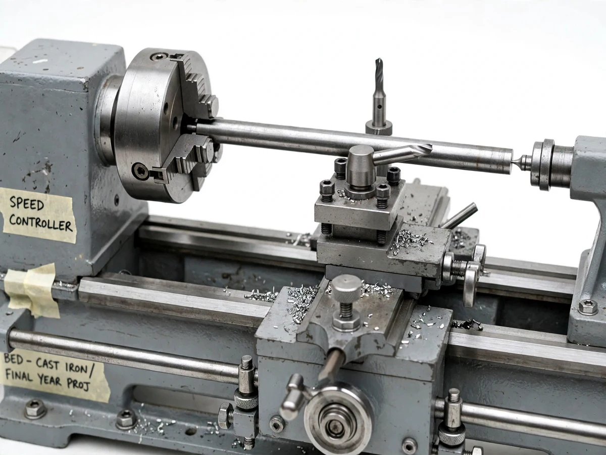
A mini lathe machine is a bench-top turning machine that shapes a rotating metal workpiece with a fixed cutting tool, and this project builds one with variable speed control and an adjustable tool rest. Most Mechanical students only operate a full-size workshop lathe under supervision, so they rarely learn how spindle speed, feed and tool position interact to decide surface finish and dimensional accuracy. A commercial mini lathe costs far more than a student budget allows, and a purely theoretical design report leaves those relationships abstract. This project closes that gap with a working machine: a 24 V DC motor (datasheet value) drives the spindle through a belt, a PWM speed controller varies spindle speed, a 3-jaw chuck (design target: 80 mm diameter) grips the workpiece, and the tool rest supports the cutting tool at the correct height. Students turn, face and drill mild-steel and aluminium parts, measure the results, and connect workshop practice to the theory of metal cutting.
Clamps the bar, sets the speed knob and feeds the tool by hand.
Follow the working sequence
How it works
The mini lathe machine spins the workpiece while a fixed cutting tool removes metal, running from setup to measurement. The operator clamps a round bar in the 3-jaw chuck, supports its free end with the live centre, and sets the tool rest so the tool sits at centre height. The 24 V DC motor drives the spindle through a V-belt, and the PWM controller sets the speed: cutting speed rises with diameter at the same spindle speed, so a 20 mm bar needs roughly twice the rpm of a 40 mm bar for the same surface speed, which is why the speed knob matters more than top speed. The operator feeds the tool into the spinning bar, takes a light cut, measures the diameter with a vernier caliper, and repeats with finer cuts until the target size is reached. Facing squares the end of the bar, and a tailstock drill bores a centre hole while the workpiece spins.
- Clamp the round bar in the 3-jaw chuck and bring the tailstock live centre up to support the free end.
- Set the adjustable tool rest so the high-speed steel cutting tool sits at the centre height of the workpiece.
- Select the spindle speed on the PWM controller knob — low speed for larger diameters, higher speed for smaller ones.
- Start the motor and feed the tool into the rotating workpiece with the carriage handwheel for the first light cut.
- Measure the turned diameter with a vernier caliper and record the reading in the test log.
- Take successive finer cuts, then face the end of the bar and drill the centre hole using the tailstock.
- Stop the motor, remove the finished part, clean the chips from the bed and check the final dimensions.
Tech stack:
- 24 V DC motor · belt drive
- PWM speed controller
- 3-jaw self-centering chuck
- Cast-iron lathe bed · ground guideways
- High-speed steel cutting tools
- Live centre · tailstock
- Mild steel · aluminium workpieces
- Vernier caliper · measurement tools
Requirements
- Hardware: 24 V DC motor (250 W, datasheet value), V-belt and pulleys, 3-jaw chuck (80 mm, design target), cast-iron bed with guideways, cross-slide with tool post, tailstock with live centre, PWM speed controller, 24 V DC adapter, high-speed steel tool bits, vernier caliper, bench vice and hand tools for assembly.
- Software: No software is required for this pure-hardware build; drawings are supplied as dimensioned diagrams and the report as a PDF.
| Parameter | Value |
|---|---|
| Drive motor | 24 V DC motor, 250 W (datasheet value) |
| Spindle speed | Approximately 100–2,500 rpm (design target, PWM-controlled) |
| Chuck | 3-jaw self-centering chuck, 80 mm diameter (design target) |
| Distance between centres | Approximately 300 mm (design target) |
| Maximum workpiece diameter | Approximately 100 mm over the bed (design target) |
| Maximum workpiece length | Approximately 250 mm between centres (design target) |
| Tool rest travel | Approximately 150 mm along the bed (design target) |
| Bed | Cast-iron bed, approximately 450 mm long (design target) |
| Power supply | 230 V AC mains via 24 V DC adapter (datasheet value) |
| Cutting tools | High-speed steel tool bits, 8 mm × 8 mm shank (design target) |
| Overall size | Approximately 600 mm × 200 mm × 250 mm (design target) |
| Weight | Approximately 18 kg (design target) |
Project features
The mini lathe machine delivers its value through four capabilities that work together: variable speed control that lets the student match spindle speed to the workpiece material and diameter, an adjustable tool rest that holds the cutting tool at the correct centre height for a clean cut, a 3-jaw self-centering chuck with a live-centre tailstock that grips and supports the workpiece securely, and a rigid cast-iron bed with ground guideways that keeps the carriage moving in a straight line. Around these four, the belt drive, the safety guard, the graduated handwheels and the measurement routine complete a machine that a student can genuinely operate, measure and explain. Every feature below is part of the base build, and the one optional item is labelled as optional rather than presented as included.
- [Variable speed control] A PWM speed controller varies the DC motor speed from a rotary knob, so the student can select low speed for large diameters and higher speed for small diameters instead of running at one fixed speed.
- [Adjustable tool rest] The tool rest slides along the bed and clamps at any position, holding the cutting tool at centre height so the tool cuts cleanly without rubbing or digging in.
- [3-jaw self-centering chuck] The 3-jaw chuck (design target: 80 mm diameter) grips round bar centrally without manual centering, and the tailstock live centre supports the free end of longer workpieces.
- [Rigid cast-iron bed] A cast-iron bed with ground guideways carries the carriage and tailstock in a straight line, reducing vibration and keeping turned diameters consistent along the length.
- [Belt drive with guard] A V-belt connects the motor to the spindle and a simple guard covers the drive, so the transmission is visible for study yet protected during operation.
- [Graduated handwheels] Handwheels on the cross-slide and carriage let the student set depth of cut and feed position in small, repeatable steps and record the settings in the test log.
- [Turning, facing and drilling] The machine performs plain turning, facing and centre drilling on mild steel and aluminium, covering the three basic lathe operations taught in workshop practice.
- [Optional thread-cutting attachment] Thread cutting is an optional customization, not part of the base build: a change-gear set and lead screw can be added on request for screw-thread demonstrations.
What is included
- Working mini lathe machine prototype with variable speed control and tool rest
- Dimensioned drawings of the bed, headstock, carriage and tailstock
- Component list with specifications and sourcing notes
- Assembly and alignment procedure
- Test procedure with a measurement log sheet for turned parts
- Project report PDF (background, metal-cutting theory, design, methodology, results)
- PPT presentation for final review
- Viva Q&A preparation document (turning operations, cutting speed, feed, tool geometry, safety)
Timeline
- Weeks 1–2: Design, calculations and dimensioned drawings of the bed, headstock and carriage.
- Weeks 3–4: Fabrication of the bed, frame and guideways; procurement of motor, chuck and controller.
- Weeks 5–6: Assembly of headstock, spindle, belt drive and tailstock; wiring of the speed controller.
- Week 7: Alignment, tool-rest setting and trial cuts on mild steel and aluminium.
- Week 8: Final measurement, report writing, PPT and viva preparation.
Support
- Build guidance and drawings are included with the order, and the test procedure explains every measurement the student must record.
- The report, PPT and viva Q&A are prepared for the student's own build and college format.
- Customization such as the thread-cutting attachment, a larger chuck or a digital speed display can be developed on request, based on technical feasibility and timeline, and is quoted separately.
Limitations & prerequisites
- This is a bench-top student prototype, not a production lathe: it handles only small, soft workpieces and light cuts, not heavy roughing or hardened steel.
- Spindle speed, chuck size and workpiece limits are design targets stated honestly — the report documents the actual achieved figures after the build is tested.
- Surface finish depends on tool sharpness, feed rate and operator skill; no finish value is guaranteed.
- The belt drive can slip under an excessive depth of cut; the procedure limits cuts to light passes.
- No automatic feed is included in the base build — feed is manual through the handwheels.
- The machine must be operated with safety glasses and tied-back hair, and the belt guard must stay fitted during operation.
- Mild steel and aluminium only in the base build; brass and plastics need a tool and speed check first.
Frequently Asked Questions
Is this project suitable for a final-year project?
Yes, it is suitable for Mechanical Engineering degree and Diploma Mechanical final-year projects because it demonstrates turning operations, cutting-speed and feed selection, machine design, fabrication and measurement in one working build, and the finished parts and test readings give the student real evidence to present and discuss in the viva. The report, PPT and viva Q&A are prepared for the student's own build and college format.
What can this mini lathe machine actually make?
It turns, faces and centre-drills small mild-steel and aluminium parts such as stepped shafts, pins, bushings and small rollers, working within approximately 100 mm diameter and approximately 250 mm length (design targets) and using only light cuts for safe student operation. It suits demonstration parts rather than production work, and hardened steel is out of scope for the base build.
What power supply does it need?
It runs from an ordinary 230 V AC mains socket through a 24 V DC adapter (datasheet value) that powers the motor and the PWM speed controller, so no three-phase supply, compressor or special wiring is needed and the whole machine sits on a sturdy workbench. The adapter and controller wiring are documented in the assembly procedure.
How does the variable speed control work?
A PWM speed controller varies the voltage to the 24 V DC motor from a rotary knob, changing the spindle speed across approximately 100–2,500 rpm (design target), with low speed for larger diameters and facing cuts and higher speed for small diameters. The student records the speed used for each cut in the test log, which makes speed selection a viva talking point.
Can the lathe be customized for my college requirements?
Yes, realistic customization is available on request and quoted separately, with common options including the thread-cutting attachment, a larger chuck, a digital speed display and a longer bed, while the base build, drawings and report stay as described on this page. Each option is checked for technical feasibility and timeline before it is confirmed.
Components & software requirements
- 24 V DC motor · belt drive
- PWM speed controller
- 3-jaw self-centering chuck
- Cast-iron lathe bed · ground guideways
- High-speed steel cutting tools
- Live centre · tailstock
- Mild steel · aluminium workpieces
- Vernier caliper · measurement tools
Requirements
- Hardware: 24 V DC motor (250 W, datasheet value), V-belt and pulleys, 3-jaw chuck (80 mm, design target), cast-iron bed with guideways, cross-slide with tool post, tailstock with live centre, PWM speed controller, 24 V DC adapter, high-speed steel tool bits, vernier caliper, bench vice and hand tools for assembly.
- Software: No software is required for this pure-hardware build; drawings are supplied as dimensioned diagrams and the report as a PDF.
Delivery information
Built-to-order project. Delivery timeline is shared after order confirmation based on current queue.
Support terms
Complete documentation, setup guide, and viva preparation included. Support for setup and explanation provided.
Download free synopsis (PDF)
Enter your name and WhatsApp number — the synopsis PDF downloads immediately. We may send occasional project updates on WhatsApp; no spam.