
More project photos (2)
The problem
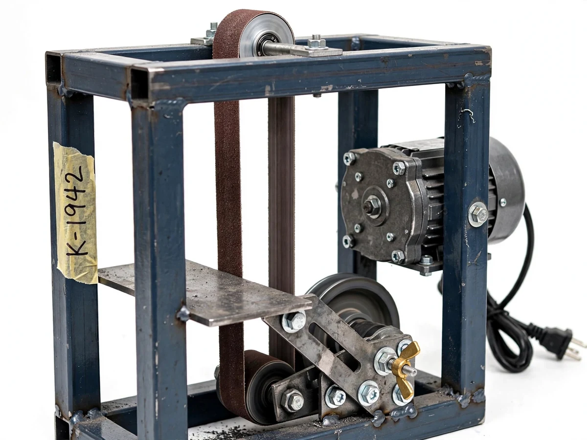
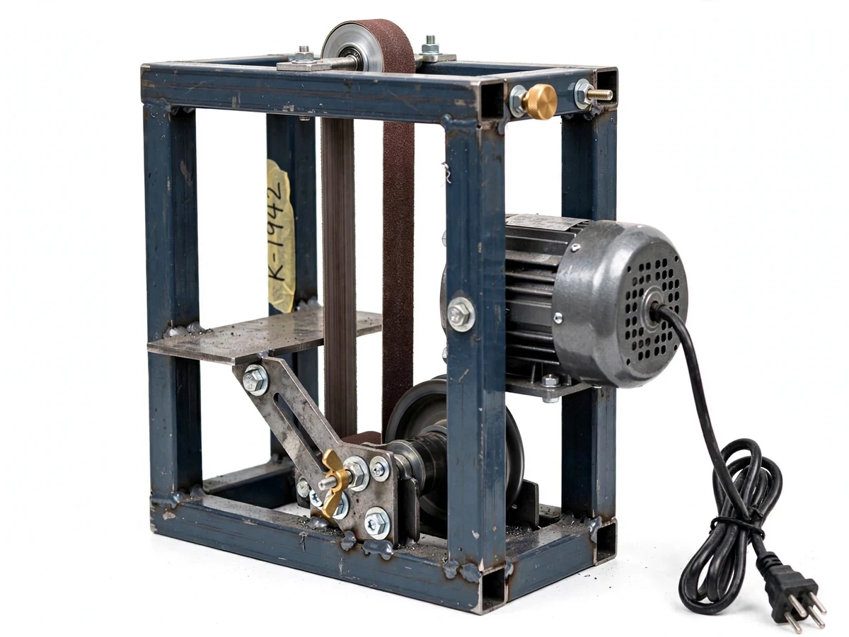
Small fabrication shops and college workshops constantly need light grinding work — deburring a cut edge, sharpening a chisel or drill, chamfering a small bracket. Bench grinders with stone wheels are common, but they run hot, glaze easily and give the operator no control over the grinding angle. Abrasive belt grinders cut faster and cooler, yet commercial mini belt grinders are expensive and their work rests are usually fixed at 90 degrees, which is the wrong angle for bevels and tool sharpening. This project closes that gap by designing and fabricating a compact benchtop belt grinder whose work-rest table tilts and locks anywhere from 0 to 45 degrees. The machine is sized for a workbench, runs on a single-phase socket, and is built entirely from MS fabrication and off-the-shelf rollers, bearings and a motor — so the student owns every part of its design, from belt-speed calculations to the angle fixture.
Single-phase 230 V supply with switch feeding the induction motor.
Follow the working sequence
How it works
- The 230 V supply powers the 0.5 HP induction motor, which spins the drive roller at approximately 1440 rpm (design target) through a direct shaft coupling.
- The drive roller carries the 25 mm wide abrasive belt around the contact roller; the tracking knob and tension screw are adjusted until the belt runs centered and taut.
- The work-rest table is loosened at the wing-nut clamp, tilted to the required grinding angle against the angle scale, and re-tightened.
- The operator holds the workpiece flat on the work-rest and feeds it lightly into the moving belt; the belt removes material through abrasive cutting.
- Light, repeated passes with cooling intervals are used — the belt cuts faster and cooler than a stone wheel, but the workpiece is still checked for heat.
- Grinding dust falls onto the bench area, which is cleaned after the session; the belt is inspected for wear and the machine is switched off once the rollers stop.
Tech stack:
- MS square-tube frame · MIG/ARC welding
- 0.5 HP single-phase induction motor
- 25 x 762 mm aluminium-oxide abrasive belt
- Drive roller + contact roller on bearing blocks
- Slotted angle-adjustable work-rest fixture
- Belt tensioning · tracking screw assembly
- Drilling · tapping · bench fitting
- 230 V single-phase wiring with switch
| Parameter | Value |
|---|---|
| Drive motor | 0.5 HP single-phase induction motor, approx. 370 W (design target) |
| Motor speed | Approx. 1440 rpm (design target) |
| Abrasive belt | 25 x 762 mm aluminium-oxide belt, 80 grit (design target) |
| Belt speed | Approx. 10-15 m/s (design target, component-dependent) |
| Work-rest angle | 0-45 degrees adjustable, wing-nut clamp (design target) |
| Work-rest table | MS plate on slotted support bracket |
| Rollers | Drive roller + contact roller on pillow-block bearings, approx. 50 mm dia. (design target) |
| Frame | MS square-tube welded frame, painted |
| Power supply | 230 V single-phase |
| Overall size | Approx. 450 x 300 x 450 mm (design target) |
| Weight | Approx. 18-22 kg (expected) |
Project features
- [Adjustable-angle work-rest] The steel work-rest table tilts and locks at any angle from 0 to 45 degrees using a slotted support bracket with a wing-nut clamp, so chamfers, bevels and tool edges are ground at repeatable angles.
- [Belt-drive grinding head] A 0.5 HP single-phase induction motor drives a narrow 25 mm aluminium-oxide abrasive belt over drive and contact rollers, giving a fast, cool-running material-removal surface.
- [Manual belt tracking and tensioning] A threaded tracking knob and tension screw keep the belt centered on the rollers; setting and adjusting them is part of the documented setup procedure.
- [Welded MS frame] The compact frame is fabricated from MS square tube with welded joints and bolted bearing blocks for the roller shafts, sized for benchtop rigidity.
- [Multi-operation grinding] One rig covers surface grinding, edge deburring, drill and chisel sharpening and small-part finishing — the common light grinding jobs of a teaching workshop.
- [Guarded belt run] Fabricated sheet-metal guards cover the non-working belt sections while leaving the work zone open, keeping fingers and clothing clear of the moving belt.
- [Benchtop footprint] The machine sits on a workbench with an approximately 450 x 300 mm footprint, needs only a 230 V single-phase socket, and can be carried between lab bays.
What is included
- Working benchtop mini belt grinder prototype with adjustable work-rest
- Fabrication drawings: frame, roller shafts, bearing blocks, work-rest fixture
- Belt-drive calculation sheet: belt speed, tension and power estimates
- Angle-setting and belt-tracking adjustment procedure
- Project report PDF, presentation PPT and viva Q&A document
- Safety, maintenance and belt-replacement checklist
Limitations & prerequisites
- This is a student prototype for light, intermittent grinding — it is not an industrial-grade machine and is not rated for continuous production duty.
- Belt tracking drifts with use and must be re-adjusted periodically with the tracking knob; a misaligned belt can run off the rollers.
- Grinding dust is generated in the open; the operator must wear a dust mask and eye protection, and the area must be cleaned after use.
- There is no coolant system, so the workpiece can heat up — only light passes with cooling intervals are advised.
- Abrasive belts are consumables: grit wears with use and belts must be replaced, budgeted as running cost.
- Vibration depends on roller balance and alignment quality; the student verifies smooth running during commissioning.
- Grinding noise makes this a workshop-only machine, not suitable for classrooms or indoor labs.
Frequently Asked Questions
What can actually be ground on this machine?
Mild-steel edges, small brackets, chisel and drill sharpening, deburring cut parts and light surface finishing. It is sized for small parts, not heavy stock removal or large forgings.
How is the work-rest angle adjusted?
Loosen the wing-nut clamp, tilt the table against the angle scale to the required angle between 0 and 45 degrees, and re-tighten. The slotted bracket holds the setting during grinding.
What power supply does it need?
A standard 230 V single-phase socket. The 0.5 HP motor draws under 2 A, so no special wiring is required.
Does the belt need regular attention?
Yes — tracking is manual and drifts with use, so the tracking knob is adjusted as part of the documented setup procedure, and worn belts are replaced with the same 25 x 762 mm size.
What are the main limitations?
Intermittent duty only (no continuous production use), open dust generation requiring a mask and eye protection, no coolant, consumable belts, and workshop-only noise levels.
Is this project suitable for a final-year project?
Yes — for Mechanical, Production and Industrial engineering. It demonstrates machine fabrication, belt-drive design, fixture design with the adjustable work-rest, and safe workshop practice, all documented for the viva. Suitable for B.E./B.Tech final-year projects in Mechanical, Production and Industrial engineering.
Components & software requirements
- MS square-tube frame · MIG/ARC welding
- 0.5 HP single-phase induction motor
- 25 x 762 mm aluminium-oxide abrasive belt
- Drive roller + contact roller on bearing blocks
- Slotted angle-adjustable work-rest fixture
- Belt tensioning · tracking screw assembly
- Drilling · tapping · bench fitting
- 230 V single-phase wiring with switch
Delivery information
Built-to-order project. Delivery timeline is shared after order confirmation based on current queue.
Support terms
Complete documentation, setup guide, and viva preparation included. Support for setup and explanation provided.
Download free synopsis (PDF)
Enter your name and email — the synopsis PDF downloads immediately. We may send occasional project updates; no spam, unsubscribe anytime.