
More project photos (2)
The problem
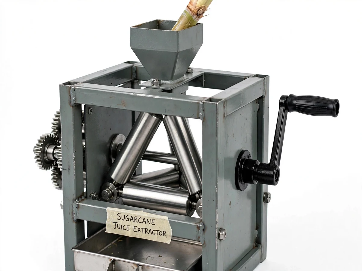
Roadside sugarcane juice vendors and small farm households typically extract juice with either a two-roller hand crusher that must be re-fed several times or a heavy motorized mill that needs electricity and costs far more. Both extremes leave a gap: a low-cost, electricity-free extractor that squeezes more juice per pass than a basic two-roller unit. This project addresses that gap with a manual-crank machine using three rollers arranged in a triangle — the cane is drawn between the top roller and the first bottom roller, then immediately crushed a second time between the top roller and the second bottom roller in a single feed. That double crushing in one pass raises expected juice recovery compared with a single-nip design while keeping the machine fully human-powered, portable and buildable with standard workshop processes (turning, milling, welding and gear fitting). Because every part — rollers, gears, frame, crank and bearings — is selected and dimensioned during the design stage, the project gives a mechanical engineering student genuine practice in machine design, power-transmission calculation and fabrication.
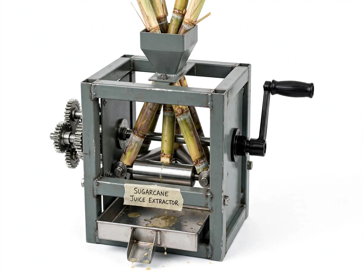
Operator feeding cane, turning the crank and collecting juice.
Follow the working sequence
How it works
- A peeled sugarcane stalk is fed through the top guide chute so its end sits in the first nip between the top roller and the front bottom roller.
- The operator turns the hand crank; the crank pinion drives a spur-gear train that reduces speed and multiplies torque to the roller shafts.
- All three rollers rotate inward together, gripping the cane and drawing it through the first nip, where the primary crushing squeeze happens.
- The cane passes immediately into the second nip (top roller against the rear bottom roller) for a second press without re-feeding.
- Expressed juice runs down the roller faces into the stainless collection tray and out through the pouring spout.
- The flattened bagasse exits the rear of the roller block, away from the juice path.
- For drier bagasse, the stalk can be passed a second time with the roller gap set slightly tighter.
Tech stack:
- SolidWorks (3D modelling & assembly drawings)
- SS304 stainless steel (roller & juice-contact parts)
- Mild steel IS 2062 (welded frame)
- Spur gear pair with crank pinion (power transmission)
- Pillow-block / screw-adjustable bearings
- MIG welding
- Lathe turning & milling
- Enamel paint coating (frame corrosion protection)
| Parameter | Value |
|---|---|
| Roller arrangement | 3 rollers, triangular (1 top, 2 bottom) |
| Roller material | SS304 stainless steel, polished (design choice) |
| Roller diameter | Approximately 75–90 mm (design target) |
| Roller working length | Approximately 120–150 mm (design target) |
| Frame | Welded mild-steel square tube, enamel painted |
| Drive | Manual crank → spur-gear reduction train (design target ratio ≈ 1:4 to 1:6) |
| Roller gap | Adjustable via screw blocks, approximately 0–10 mm (design target) |
| Cane size | Stalks approximately 20–40 mm diameter (expected range) |
| Throughput | Approximately 8–15 kg cane per hour (design target, operator-dependent) |
| Juice recovery | Typically 40–60% of cane weight (expected range for manual three-roller units; varies with cane freshness and gap setting) |
| Overall size | Approximately 550 × 350 × 450 mm (design target) |
| Weight | Approximately 25–35 kg (expected, fabrication-dependent) |
Project features
- [Triangular three-roller crushing arrangement] Two crushing nips in a single feed — the top roller works against each of the two bottom rollers in turn — so the cane is pressed twice without re-feeding (implemented geometry).
- [Manual crank with gear-reduction drive] A hand crank drives the roller train through a spur-gear reduction so one person can develop enough roller torque to crush cane of typical roadside diameter (implemented).
- [Adjustable roller gap] Screw-type bearing blocks let the roller gap be set for thin or thick cane and for re-tightening as rollers wear (implemented, configurable at build).
- [SS304 food-contact rollers] The three rollers are turned from SS304 stainless steel, polished smooth, since every cane-contact surface should be food-grade (implemented).
- [Juice tray with pouring spout] A formed stainless tray under the roller block collects expressed juice and routes it to a spout for clean filling of a glass or jug (implemented).
- [Bagasse discharge path] Crushed cane (bagasse) exits the opposite side of the roller block clear of the juice tray, keeping juice and residue separated (implemented).
- [Rigid mild-steel frame] A welded square-tube frame with bolted bearing housings carries roller and gear loads without flexing during cranking (implemented).
What is included
- Working three-roller sugarcane juice extraction prototype with manual crank
- Fabrication report PDF (design calculations, gear ratio selection, roller and shaft sizing, assembly procedure)
- 2D fabrication drawings and 3D assembly model files
- Component list with material specifications
- Assembly and operating instructions
- Abstract PDF (10-section project abstract)
- PPT presentation for final review
- Viva Q&A preparation document (machine design, gearing, bearings, fabrication processes)
Limitations & prerequisites
- Fully manual — throughput depends on operator effort and stamina; it cannot match a motorized mill's output.
- Juice recovery is lower than commercial hydraulic presses; stated recovery is an expected range, not a measured guarantee.
- Bagasse from a single pass still holds some juice; very dry bagasse needs a second pass at a tighter gap.
- Cane thicker than the expected range or heavily dried cane can jam the nip and must be split or trimmed first.
- The prototype is an academic fabrication project, not a food-safety-certified commercial machine — hygiene of juice handling is the buyer's responsibility.
- Roller gap must be re-checked periodically as the screw blocks can shift under repeated loading.
Frequently Asked Questions
How is a three-roller machine better than a two-roller one?
A two-roller crusher gives one crushing nip per feed, so vendors re-feed cane two or three times. The triangular three-roller layout creates two nips, so one feed crushes the cane twice. The expected result is higher juice recovery per pass and less re-feeding, at the cost of a slightly more complex gear train.
Can a single person operate it?
Yes — that is the design point. The gear-reduction train between the crank and the rollers multiplies the operator's torque, so steady cranking with one hand (the other hand feeding cane) is enough for typical 20–40 mm stalks. Very thick or dry cane may need two-handed cranking or pre-splitting.
Why SS304 for the rollers?
Every surface that touches the cane and juice should be food-grade and corrosion-resistant. SS304 polishes smooth (easier cleaning, less juice staining) and will not rust the way plain steel rollers would after repeated washing.
What maintenance does it need?
Wipe and rinse the rollers and tray after each use, keep the gear train lightly greased, and check the roller-gap screws periodically. The frame is enamel-painted mild steel, so chips should be touched up to prevent rust.
Can it be motorized later?
The frame and bearing layout allow a motor-and-belt retrofit as an optional customization — the crank shaft can be replaced with a pulley drive. Motorization is not part of the base build and is quoted separately.
Is this project suitable for a final-year project?
Yes — for Mechanical Engineering programs. It demonstrates machine design (shaft and roller sizing), power transmission (gear ratio selection), bearing selection, and real fabrication (turning, milling, welding, assembly), all documented for the viva. Suitable for B.E./B.Tech final-year projects in Mechanical Engineering.
Components & software requirements
- SolidWorks (3D modelling & assembly drawings)
- SS304 stainless steel (roller & juice-contact parts)
- Mild steel IS 2062 (welded frame)
- Spur gear pair with crank pinion (power transmission)
- Pillow-block / screw-adjustable bearings
- MIG welding
- Lathe turning & milling
- Enamel paint coating (frame corrosion protection)
Delivery information
Built-to-order project. Delivery timeline is shared after order confirmation based on current queue.
Support terms
Complete documentation, setup guide, and viva preparation included. Support for setup and explanation provided.
Download free synopsis (PDF)
Enter your name and email — the synopsis PDF downloads immediately. We may send occasional project updates; no spam, unsubscribe anytime.