
More project photos (2)
The problem
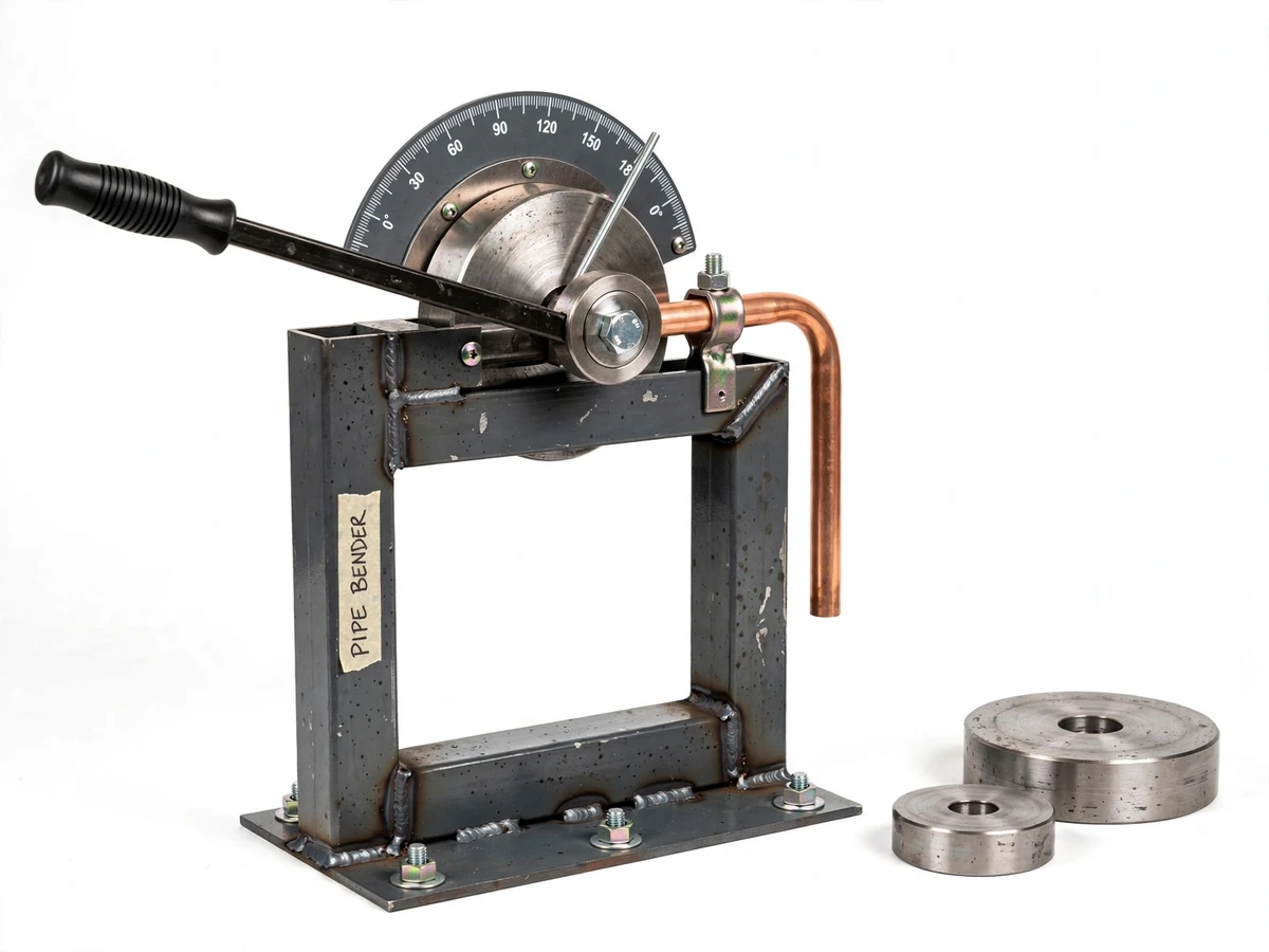
Small workshops, plumbers and college fabrication labs bend metal tube almost every day — handrail frames, chair legs, exhaust routing, HVAC piping and cycle racks all need curved tube. Without a proper bender, tube is bent over a knee or a mandrel-like edge, which flattens the cross-section, kinks the wall, or produces a different angle every time. Commercial mandrel benders solve this but cost far more than a student budget allows, and they usually ship with only one die size. This project takes the practical middle path: a hand-operated rotary-draw bender fabricated from mild-steel sections in a college workshop, with a set of interchangeable former dies so one machine handles the tube sizes students actually use, and a graduated angle scale with a pointer that turns bending from guesswork into a measured operation.
Operator selecting dies, clamping tube and pulling the lever.
Follow the working sequence
How it works
- The operator selects the former die matching the tube outside diameter and seats it on the main pivot pin, fixing it with the retaining nut.
- A length of tube is marked at the bend point, slid into the die groove, and locked by the clamp so it cannot slip or twist during the bend.
- The 0° mark on the scale is aligned with the pointer, with an overbend allowance added for the tube's springback (the operating procedure explains the buyer-run trial-bend calibration).
- Pulling the long lever rotates the former die, drawing the tube around the grooved radius while the pressure block supports the back of the wall.
- The pointer sweeps the graduated scale; the operator stops the pull at the target angle on the dial.
- Releasing the clamp and lifting the tube off the die reveals a bend with its angle read directly from the scale and its radius set by the die groove.
- A simple trial-bend procedure, run by the buyer on offcut tube, fixes the overbend allowance for their specific tube material and thickness.
Tech stack:
- Manual rotary-draw bending (no hydraulics)
- Mild-steel fabrication · arc welding
- Lathe-turned interchangeable former dies
- Graduated 0–180° bending angle scale
- Mechanical advantage of the lever arm
- 2D fabrication drawings (AutoCAD/Fusion sketch)
- Springback compensation procedure
- Dimensional inspection with vernier/dial tools
| Parameter | Value |
|---|---|
| Compatible tube outside diameter | 15, 20, 25, 32 mm (one die per size) |
| Maximum bend angle | 180° (graduated scale 0–180°) |
| Lever handle length | Approximately 1.2 m (design target) |
| Frame | MS square tube 50 × 50 × 3 mm, welded, gusseted |
| Former dies | Machined steel, one groove per die |
| Pivot pin | Steel shaft with retaining nut |
| Wall thickness (design target) | Up to ~2 mm copper/annealed aluminium; up to ~1.6 mm MS tube |
| Centerline bend radius (design target) | Approximately 3 × tube OD per die groove |
| Base | MS plate with 4 anchor holes |
| Bend angle accuracy | Operator-read from scale; buyer-run trial bends fix the springback allowance |
| Ovality | Design target below ~8% on thin-wall copper (measured by the buyer with a vernier during commissioning) |
Project features
- [Interchangeable former dies] A set of machined steel dies with grooves sized for 15, 20, 25 and 32 mm outside-diameter tube; each die drops onto the same pivot pin, so changing tube size takes a minute and no re-fabrication.
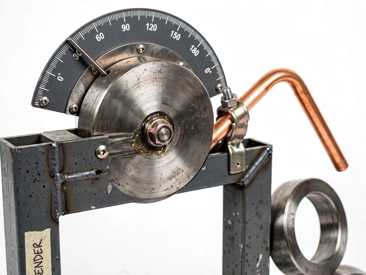
- [Bending angle scale] A 0–180° graduated scale arc mounted behind the die head with a pointer fixed to the rotating die, letting the operator bend to a chosen angle instead of estimating by eye.
- [Long lever handle] A steel lever roughly 1.2 m long with a rubber grip, giving the mechanical advantage needed for single-operator bending of thin-wall tube without a cheater bar or a second person.
- [Tube clamp and pressure block] A bolted clamp holds the tube against the die so it cannot slip or rotate during the draw, which is what keeps the bend centered on the marked line.
- [Welded MS frame] The stand is built from square mild-steel tube with gusseted joints and a bolted base plate, stiff enough that the frame absorbs the bending reaction instead of flexing.
- [Kink-resistant rotary-draw action] The tube is drawn around the grooved former die rather than folded against an edge, so the groove supports the wall and the ovality stays low compared with freehand bending.
- [Workshop-fabricable construction] Every part — frame, pivot, dies, clamp, scale — is made with college-workshop processes: cutting, arc welding, drilling and lathe turning. No casting, no CNC.
What is included
- Working fabricated pipe-bending prototype with one former die fitted
- Full set of interchangeable former dies (15, 20, 25, 32 mm tube)
- Fitted 0–180° bending angle scale with pointer
- Pipe clamp and pressure block assembly
- 2D fabrication drawings of every part with dimensions
- Bill of materials with standard steel sections and fasteners
- Trial-bend and springback calibration procedure
- Project report PDF (theory, design calculations, fabrication process, results)
- PPT presentation for final review
- Viva Q&A preparation document (bending mechanics, springback, die design, welding)
Limitations & prerequisites
- Bend angle and ovality values are design targets — the buyer runs the trial-bend procedure on their own tube to establish actual figures; nothing on this page claims a measured test result.
- Springback varies with tube material, wall thickness and temper, so the overbend allowance must be re-calibrated whenever the tube changes.
- Thin-wall or soft-temper tube can still flatten if bent past the die's design radius; tight bends in thin tube need a filled-wall technique, documented in the operating guide.
- Manual operation means bend speed is operator-dependent; there is no powered feed for production-rate work.
- Die grooves are sized for nominal tube OD; oversize or out-of-round stock tube seats poorly and degrades bend quality.
- The prototype is a workshop educational machine, not an industrially certified production bender.
- Frame and dies are unpainted steel on delivery unless the buyer requests a painted finish.
Frequently Asked Questions
Which tube sizes can this bender handle?
Four outside diameters: 15, 20, 25 and 32 mm, each with its own machined former die. Dies swap onto the same pivot pin in about a minute, so one machine covers the tube sizes used in most student and small-workshop jobs.
How does the angle scale deal with springback?
The 0–180° scale reads the die rotation directly, but tube springs back a few degrees after the lever is released. The operating procedure has the buyer make 2–3 trial bends on offcut tube and note the springback, then add that overbend allowance to the target angle — a standard workshop practice.
Will the tube kink or flatten?
The rotary-draw action pulls the tube around a grooved former die that supports the wall through the bend, which is exactly what prevents the kinking seen in freehand bending. Ovality stays low on correctly sized tube; the guide states the wall-thickness limits where thin tube still needs care.
What fabrication skills does the build demonstrate?
Cutting and arc welding of MS sections, lathe turning of the dies, drilling and tapping, basic 2D drafting, and dimensional inspection — a complete mechanical fabrication project from drawing to working machine.
What will I receive with the project?
The fabricated bender with all four dies, the angle scale fitted, full 2D fabrication drawings, bill of materials, the trial-bend calibration procedure, report PDF, PPT and a viva Q&A document.
Is this project suitable for a final-year project?
Yes — for Mechanical Engineering, and also for Production and Manufacturing programs. It demonstrates machine design, fabrication processes, bending mechanics and measurement, all as a working prototype. Suitable for B.E./B.Tech final-year projects in Mechanical Engineering.
Components & software requirements
- Manual rotary-draw bending (no hydraulics)
- Mild-steel fabrication · arc welding
- Lathe-turned interchangeable former dies
- Graduated 0–180° bending angle scale
- Mechanical advantage of the lever arm
- 2D fabrication drawings (AutoCAD/Fusion sketch)
- Springback compensation procedure
- Dimensional inspection with vernier/dial tools
Delivery information
Built-to-order project. Delivery timeline is shared after order confirmation based on current queue.
Support terms
Complete documentation, setup guide, and viva preparation included. Support for setup and explanation provided.
Download free synopsis (PDF)
Enter your name and email — the synopsis PDF downloads immediately. We may send occasional project updates; no spam, unsubscribe anytime.