
More project photos (3)

The problem
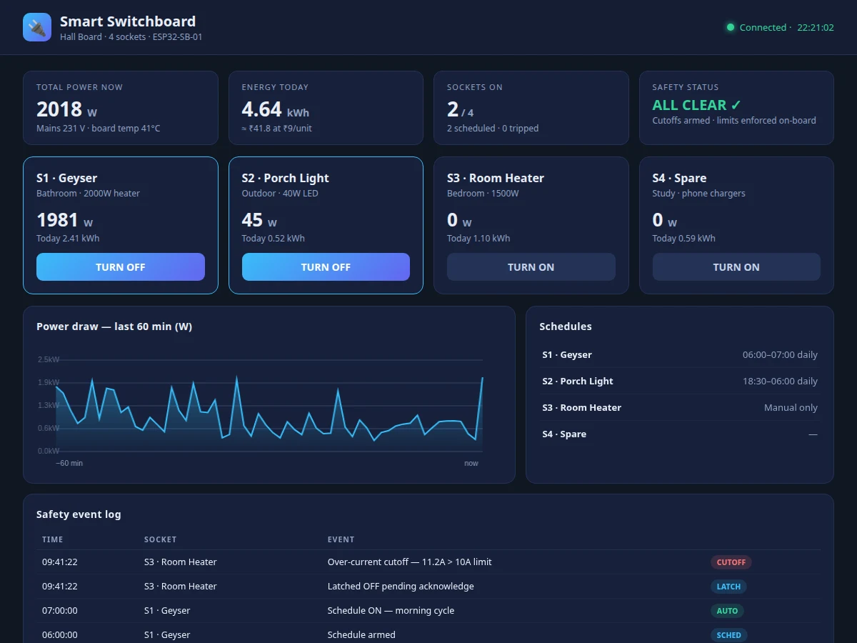
A conventional switchboard is dumb: every socket is either on or off at the wall, nobody knows what each one consumes, and a forgotten room heater runs all night. Smart plugs solve this one socket at a time, expensively. This project rebuilds the switchboard itself as the smart device: an ESP32 drives a relay per socket, a metering front-end measures voltage, current and energy for the board (and per socket where wired), and capacitive touch pads plus physical switches keep local control familiar. Safety is engineered in, not bolted on — firmware cuts any socket that exceeds its current or temperature limit, independent of the cloud. The web dashboard shows every socket's state, live power, energy history and schedules, and lets the owner toggle sockets remotely. Hardware and dashboard are both built for this project.
The board's mains incomer feeding one relay per socket.
Follow the working sequence
How it works
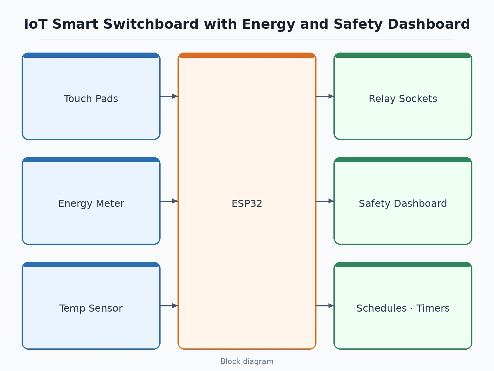
- The board wires as a normal switchboard: mains in, one relay per socket out, with the metering front-end sensing voltage and each socket's current.
- The ESP32 reads touch pads, rocker switches and dashboard commands, arbitrates them with a fixed priority (physical > app), and drives the relays.
- Current and temperature are sampled continuously; any socket crossing its over-current or over-temperature limit is cut by firmware within milliseconds and latched off with a dashboard safety event.
- Energy per socket accumulates in non-volatile counters and publishes over Wi-Fi to the dashboard every few seconds.
- The dashboard renders socket states, live power bars, energy history charts, schedules and the safety log; toggles and schedules publish back as commands.
- Schedules run from the ESP32's RTC-synced clock so timers survive short network drops.
- The student calibrates the metering channels against a known load with the included procedure before demo readings are trusted.
Tech stack:
- ESP32 development board (Wi-Fi)
- Relay board: one relay per socket (mains-rated)
- Energy metering front-end (voltage + current sensing)
- Capacitive touch pads + rocker switches
- Temperature sensor on relay bank
- Arduino IDE (C/C++ firmware)
- MQTT/HTTP telemetry + command channel
- Single-file HTML/CSS/JS dashboard
| Parameter | Value |
|---|---|
| Sockets | 4 relay-controlled sockets (design) |
| Relay rating | 230 V AC, 10 A per channel (datasheet, selected part) |
| Metering | Voltage + per-socket current; real power and kWh (design) |
| Safety limits | Over-current + over-temperature cutoff in firmware (design target) |
| Control | Touch pads + rockers + dashboard/app, fixed priority (design) |
| Schedules | Daily on/off + countdown timers, RTC-backed (design) |
| Dashboard | Single-file web app: states, power, energy, safety log (built for this project) |
| Calibration | Buyer-run known-load procedure included |
Project features
- [Per-socket relay control] Each socket is switched by its own relay driven from the ESP32, so every point can be toggled, scheduled or interlocked independently from the wall, touch pad or app.
- [Energy metering] A metering front-end measures mains voltage and per-socket (or per-board) current, computing real power and cumulative energy shown live on the dashboard.
- [Safety cutoff in firmware] Over-current and over-temperature limits are enforced on the board itself: a socket exceeding its limit is cut immediately and latched off until acknowledged, even with no network.
- [Touch + physical + app control] Capacitive touch pads, familiar rocker switches and the dashboard/app all drive the same relays, so the board stays usable during Wi-Fi outages.
- [Schedules and timers] Sockets follow daily on/off schedules and countdown timers (geyser mornings, porch light evenings) configured from the dashboard.
- [Live safety dashboard] The single-file web dashboard shows every socket's state, live power, energy charts, temperature, and a safety event log of every cutoff.
- [Manual override] A master bypass keeps essential sockets powered regardless of schedules or app state — demonstrated as the fail-safe path.
What is included
- Wired IoT smart switchboard (4 sockets, relays, touch pads, metering)
- ESP32 firmware with safety cutoff, schedules and telemetry
- Working single-file web dashboard (socket control, energy, safety log)
- Cloud telemetry + command setup guide
- Buyer-run metering calibration procedure
- Project report PDF (relay driving, metering theory, safety design, methodology)
- PPT presentation for final review
- Viva Q&A preparation document (relay isolation, energy metering, fail-safe design)
Limitations & prerequisites
- The 10 A per-channel relay rating limits each socket; the board must not switch loads beyond it, and total board load respects the incomer MCB.
- Metering accuracy depends on the buyer-run calibration; uncalibrated readings are indicative only.
- This is a demonstration-grade panel built to wiring-practice standards, not a certified commercial product — the report states its prototype status plainly.
- Schedules need periodic time sync; long offline stretches drift the RTC.
- Installation involves mains wiring and must be done with mains isolated, following the included safety procedure.
Frequently Asked Questions
How is this different from using smart plugs?
The intelligence lives in the switchboard itself: every socket is relay-controlled, metered and scheduled from one board and one dashboard, instead of one plug — and one app — per appliance.
What happens if the Wi-Fi goes down?
Everything local keeps working: touch pads, rocker switches, schedules and the safety cutoff all run on the ESP32. Only remote app control and cloud history pause.
How does the safety cutoff work?
Firmware samples each socket's current and the relay-bank temperature continuously; crossing a limit cuts that socket within milliseconds, latches it off, and logs a safety event on the dashboard until you acknowledge it.
Can I still use it like a normal switchboard?
Yes — rocker switches and touch pads drive the relays directly with the highest priority, and a master bypass keeps essential sockets on regardless of schedules.
How accurate is the energy metering?
The metering front-end is calibrated by the student against a known load with the included procedure; the report documents the achieved error honestly rather than claiming a figure.
Is this project suitable for a final-year project?
Yes — for IoT, Embedded and Electrical programs. It demonstrates mains switching, energy metering, fail-safe firmware design and a complete working dashboard. Suitable for B.E./B.Tech final-year projects in IoT, Embedded Systems and Electrical engineering.
Components & software requirements
- ESP32 development board (Wi-Fi)
- Relay board: one relay per socket (mains-rated)
- Energy metering front-end (voltage + current sensing)
- Capacitive touch pads + rocker switches
- Temperature sensor on relay bank
- Arduino IDE (C/C++ firmware)
- MQTT/HTTP telemetry + command channel
- Single-file HTML/CSS/JS dashboard
Delivery information
Built-to-order project. Delivery timeline is shared after order confirmation based on current queue.
Support terms
Complete documentation, setup guide, and viva preparation included. Support for setup and explanation provided.
Download free synopsis (PDF)
Enter your name and WhatsApp number — the synopsis PDF downloads immediately. We may send occasional project updates on WhatsApp; no spam.