
More project photos (3)
The problem
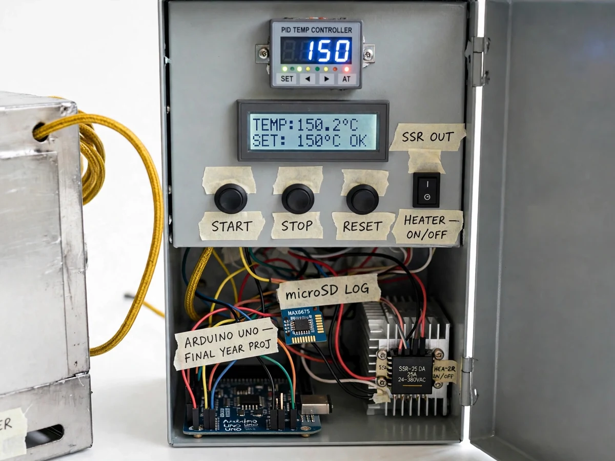
Small industrial ovens used for drying, curing and heat treatment need their chamber held at one steady temperature for hours, but a simple on-off thermostat lets the temperature swing several degrees above and below the setpoint on every cycle, and that swing spoils drying runs and heat-treatment cycles that depend on a stable soak. The Industrial Oven Temperature Controller with PID and Data Logging answers this with a bench-built oven controller: a K-type thermocouple measures the chamber temperature, an Arduino Uno runs a PID loop that switches a 500 W heater through a solid-state relay in short pulses instead of slamming it fully on or off, and a 16x2 LCD shows the live temperature against the setpoint. Every reading is written to a microSD card once every 10 seconds, so the full heat-up and soak curve can be plotted afterwards and the controller's behaviour proved from the log rather than claimed from a single display reading.
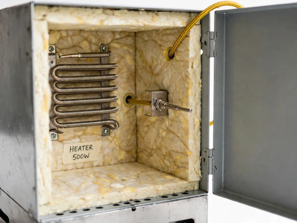
Measures the chamber temperature at mid-chamber height, clear of the heater
Follow the working sequence
How it works
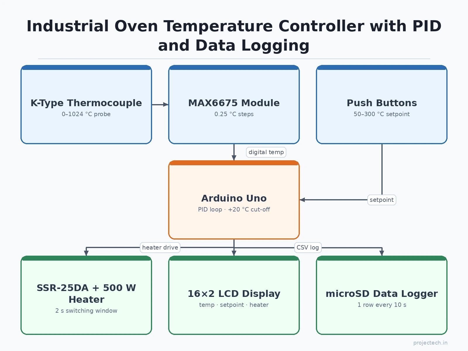
The Industrial Oven Temperature Controller with PID and Data Logging works as a closed sense-decide-switch loop that repeats several times a second. The K-type thermocouple tip sits at mid-chamber height, clear of the heater element, and its millivolt signal travels to the MAX6675 module, which applies cold-junction compensation and returns a digital temperature in 0.25 degree steps over SPI. The Arduino Uno compares that reading with the setpoint entered on the push buttons and runs the PID calculation, which produces an output between 0 and 100 percent from the size of the error, its history and its rate of change. That output sets how much of each 2 second switching window the solid-state relay stays on, so the 500 W heater receives smooth, proportional power instead of full-on or full-off bursts. The LCD refreshes with the live temperature, the setpoint and the heater state, and once every 10 seconds the logger writes the reading to the microSD card.
- The operator sets the target temperature with the push buttons; the setpoint is stored in EEPROM and shown on the 16x2 LCD.
- The K-type thermocouple measures the chamber temperature and the MAX6675 module converts it to a digital reading in 0.25 degree steps.
- The Arduino Uno runs the PID calculation on the error between the measured temperature and the setpoint, producing an output from 0 to 100 percent.
- The output drives the SSR-25DA solid-state relay in a 2 second time-proportioned window, switching the 500 W, 230 V AC heater on for the matching fraction of each window.
- The LCD updates with the live temperature, the setpoint and the heater on/off state, and the buzzer sounds if the chamber passes the over-temperature limit.
- Once every 10 seconds the firmware appends a timestamped row — elapsed time, setpoint, measured temperature and heater state — to the CSV log on the microSD card.
Tech stack:
- Arduino Uno (ATmega328P)
- K-type thermocouple · MAX6675 module
- SSR-25DA solid-state relay
- 16x2 LCD · I2C adapter
- microSD card module · CSV logging
- Arduino IDE · Embedded C
- PID control · autotune
- 500 W heater · 230 V AC
| Parameter | Value |
|---|---|
| Controller | Arduino Uno, ATmega328P, 16 MHz clock |
| Temperature sensor | K-type thermocouple probe, minus 200 to plus 1,260 degrees C (datasheet) |
| Sensor tolerance | Class 2: plus or minus 2.5 degrees C or 0.75% of reading, whichever is greater (IEC 60584-1 datasheet) |
| Converter | MAX6675 module, 0 to 1,024 degrees C, 0.25 degree C resolution, 12-bit, 220 ms conversion (datasheet) |
| Thermocouple sensitivity | Approximately 41 uV per degree C (datasheet) |
| Setpoint range | 50 to 300 degrees C (design target) |
| Steady-state hold | Within plus or minus 3 degrees C of setpoint (design target) |
| Heater | 500 W, 230 V AC mica band heater (design target) |
| Heater current | Approximately 2.2 A at 230 V AC (design calculation) |
| Solid-state relay | SSR-25DA, 25 A, 24 to 480 V AC load, 3 to 32 V DC control (datasheet) |
| Switching method | Time-proportioned PID output, 2 second window (design behaviour) |
| Display | 16x2 LCD with I2C adapter |
| Data logging | microSD card, CSV file, 1 sample every 10 seconds (design behaviour) |
| Over-temperature cut-off | Setpoint plus 20 degrees C (design target) |
| Chamber | Sheet-metal box, approximately 30 x 25 x 25 cm, ceramic fibre insulation (design target) |
| Logic power | 5 V DC adapter |
| Heater power | 230 V AC mains through SSR |
Project features
The Industrial Oven Temperature Controller with PID and Data Logging is built around four capabilities that work together on every heat-up. First, the PID loop holds the chamber at the chosen setpoint by varying the heater's on-time inside a 2 second switching window, so the temperature settles smoothly instead of swinging above and below the target the way a simple thermostat does. Second, the K-type thermocouple and MAX6675 module report the chamber temperature in 0.25 degree steps, and the 16x2 LCD shows the live reading beside the setpoint and the heater state. Third, the microSD logger writes a timestamped CSV row once every 10 seconds, so the whole heat-up, soak and cool-down curve survives the run as a file. Fourth, the over-temperature alarm and cut-off switch the heater off and sound the buzzer if the chamber passes the setpoint by 20 degrees, so a stuck relay or a failed sensor cannot drive the oven without limit.
- [PID closed-loop control (Implemented)] The Arduino runs a PID loop whose Kp, Ki and Kd come from an autotune routine on the first heat-up; the output is time-proportioned through the SSR in a 2 second window, with a steady-state hold within plus or minus 3 degrees C of setpoint as the design target.
- [K-type thermocouple sensing (Implemented)] A K-type probe with a MAX6675 converter module measures the chamber from 0 to 1,024 degrees C in 0.25 degree steps, with cold-junction compensation handled on the module so no analogue calibration circuit is needed.
- [Push-button setpoint and LCD status (Implemented)] Three push buttons set the target temperature from 50 to 300 degrees C, the setpoint is stored in EEPROM so it survives a power cycle, and the 16x2 LCD shows the live temperature, the setpoint and the heater on/off state.
- [microSD CSV data logging (Implemented)] Once every 10 seconds the firmware appends one row to a CSV file on the microSD card — elapsed time, setpoint, measured temperature and heater state — so the heat-up and soak curve can be plotted in a spreadsheet after the run.
- [Over-temperature alarm and cut-off (Implemented)] If the chamber passes the setpoint by 20 degrees C, the firmware cuts the heater, sounds the buzzer and shows an alarm on the LCD; a thermal fuse in the heater line adds a second, independent layer of protection.
- [Autotune with stored tuning (Implemented)] The autotune routine runs on the first heat-up and the tuned constants are stored in EEPROM, so the controller does not need retuning on every power-up; the setpoint and constants can be re-entered from the buttons.
- [Live serial temperature plot (Implemented)] The firmware prints the temperature and setpoint over serial once per second, so the Arduino IDE serial plotter draws the heat-up curve live while the oven runs.
- [Second probe and Wi-Fi logging (Optional customization)] A second thermocouple for a different chamber zone, a MAX31855 upgrade for a wider measurement range, or ESP32-based Wi-Fi logging can be added on request as a separate customization.
What is included
- Working prototype: insulated sheet-metal oven chamber with 500 W heater and K-type probe, plus the control panel with Arduino Uno, MAX6675 module, SSR on heatsink, 16x2 LCD, push buttons and microSD module
- Complete firmware (Arduino sketch) with PID loop, autotune routine, LCD routines and CSV logging
- Circuit and wiring diagram with pin connections for the thermocouple module, SSR, LCD, buttons and microSD module
- Component list with part numbers and quantities
- Step-by-step setup, autotune and calibration instructions, including a sample log file and a plotting guide
- Project report PDF (background, PID theory, thermocouple theory, methodology, results)
- PPT presentation for final review
- Viva Q&A preparation document (PID tuning, thermocouple types, SSR switching, data logging, mains safety)
Limitations & prerequisites
- The steady-state hold of plus or minus 3 degrees C is a design target, not a measured result; the actual hold depends on tuning, insulation quality and draughts around the chamber.
- The K-type probe's Class 2 tolerance is plus or minus 2.5 degrees C or 0.75% of reading, so the 0.25 degree display resolution is not the same as accuracy and must never be quoted as such.
- The MAX6675 reads from 0 to 1,024 degrees C only, and the setpoint range is capped at 300 degrees C as a design target; the heater and chamber are not rated above that.
- Heat-up time depends on the load inside the chamber and is not claimed as a measured figure; no heat-up time is stated anywhere on this page.
- The heater runs on 230 V AC mains, so the wiring must be checked by a competent person, the oven must never be left running unattended, and this is an academic prototype, not an industrially certified oven.
- Logging is local to the microSD card only; there is no Wi-Fi, cloud dashboard or remote alert in the base build.
- Builder note from the demo build: the thermocouple tip must sit at mid-chamber height, clear of the heater element, because a tip touching the heater reads heater temperature rather than chamber air temperature.
- Builder note from the demo build: the SSR is bolted to an aluminium heatsink because even the approximately 2.2 A heater current warms the relay case noticeably, and the autotune routine deliberately overshoots the setpoint on the first heat-up while it learns the oven's response, so first-run overshoot is expected behaviour, not a fault.
Frequently Asked Questions
Is this project suitable for a final-year project?
Yes, for Electrical, Electronics and Telecommunication and Instrumentation programs. It demonstrates PID control theory, thermocouple interfacing, solid-state relay power switching, LCD and push-button interfacing and CSV data logging in one complete, explainable build, and the report covers the PID mathematics, the thermocouple characteristics and the logging format, so the viva discussion has real technical depth rather than a single borrowed circuit.
Which controller and sensor are used, and why?
An Arduino Uno (ATmega328P) with a K-type thermocouple and a MAX6675 converter module. The Uno is used because it runs the PID loop and the logging code comfortably, its 5 V logic matches the LCD and the relay control input, and its wide community support makes wiring and debugging straightforward. The K-type probe is used because its minus 200 to plus 1,260 degree C range covers any oven setpoint, and the MAX6675 is used because a K-type thermocouple produces only about 41 microvolts per degree C, so its built-in cold-junction compensation and amplification turn a millivolt-level signal into a readable digital temperature.
How accurate is the temperature control?
The design target is a steady-state hold within plus or minus 3 degrees C of the setpoint, which is a target, not a measured result. The K-type probe itself carries a Class 2 tolerance of plus or minus 2.5 degrees C or 0.75% of reading under IEC 60584-1, so the 0.25 degree display step is resolution, not accuracy. The report states the design target honestly and explains how the buyer can verify the real hold from the logged CSV data after the build.
How does the data logging work?
Once every 10 seconds the firmware appends one row to a CSV file on the microSD card, with four columns: elapsed time, setpoint, measured temperature and heater state. The card is removed and read on any PC, and the file opens directly in a spreadsheet, so the full heat-up, soak and cool-down curve can be plotted without any extra software. The log is the evidence for the controller's behaviour: it shows the rise, the overshoot and the steady hold.
Is it safe to run a 230 V heater?
Yes, with the stated precautions, because the design keeps the mains side isolated from the logic side. The SSR switches the heater with optical isolation, the relay sits on an aluminium heatsink, a thermal fuse sits in the heater line, and the firmware cuts the heater if the chamber passes the setpoint by 20 degrees C. Even so, the mains wiring must be checked by a competent person, the oven must never be left running unattended, and it remains an academic prototype, not an industrially certified oven.
Can the setpoint range or heater be changed for a different oven?
Yes, the setpoint limits, the PID constants and the switching window are constants in the firmware, so a different temperature range can be set by editing a few numbers and re-uploading the sketch, with no wiring changes. A larger heater needs an SSR and heatsink re-check, and a wider measurement range needs a MAX31855 module instead of the MAX6675. A second thermocouple for another chamber zone can be added as an optional customization.
Components & software requirements
- Arduino Uno (ATmega328P)
- K-type thermocouple · MAX6675 module
- SSR-25DA solid-state relay
- 16x2 LCD · I2C adapter
- microSD card module · CSV logging
- Arduino IDE · Embedded C
- PID control · autotune
- 500 W heater · 230 V AC
Delivery information
Built-to-order project. Delivery timeline is shared after order confirmation based on current queue.
Support terms
Complete documentation, setup guide, and viva preparation included. Support for setup and explanation provided.
Download free synopsis (PDF)
Enter your name and WhatsApp number — the synopsis PDF downloads immediately. We may send occasional project updates on WhatsApp; no spam.