
More project photos (3)
Watch it work
The problem
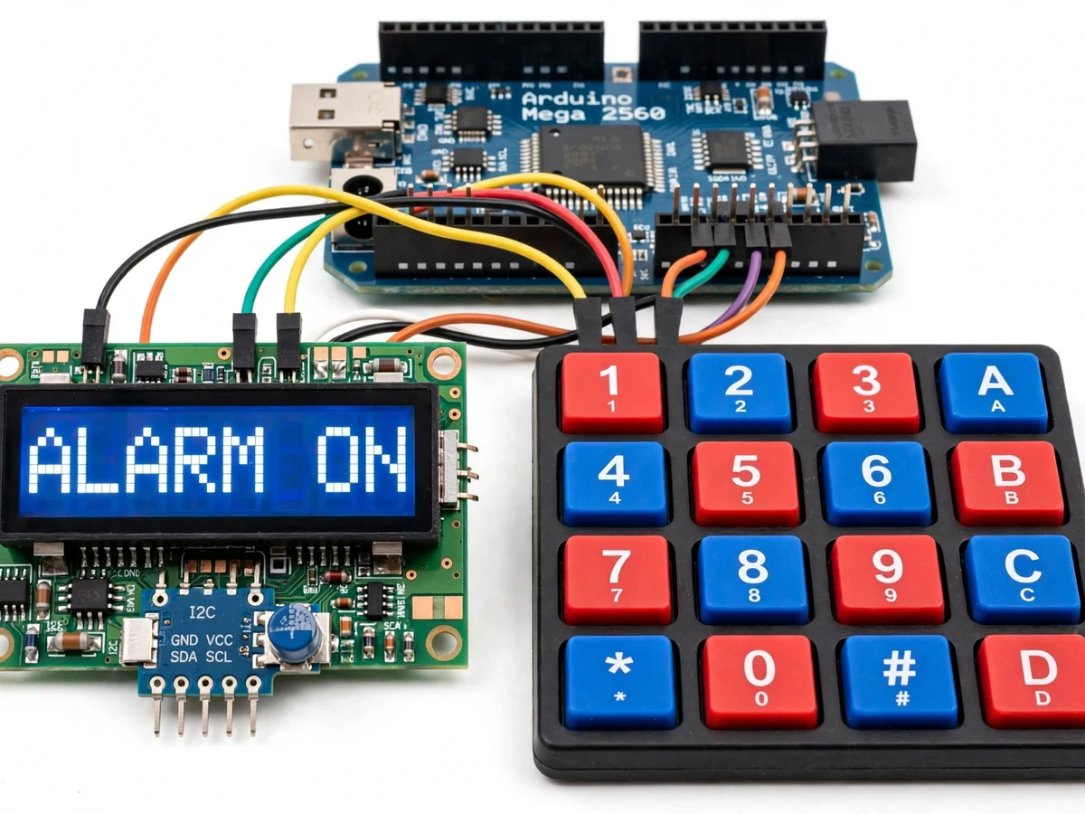
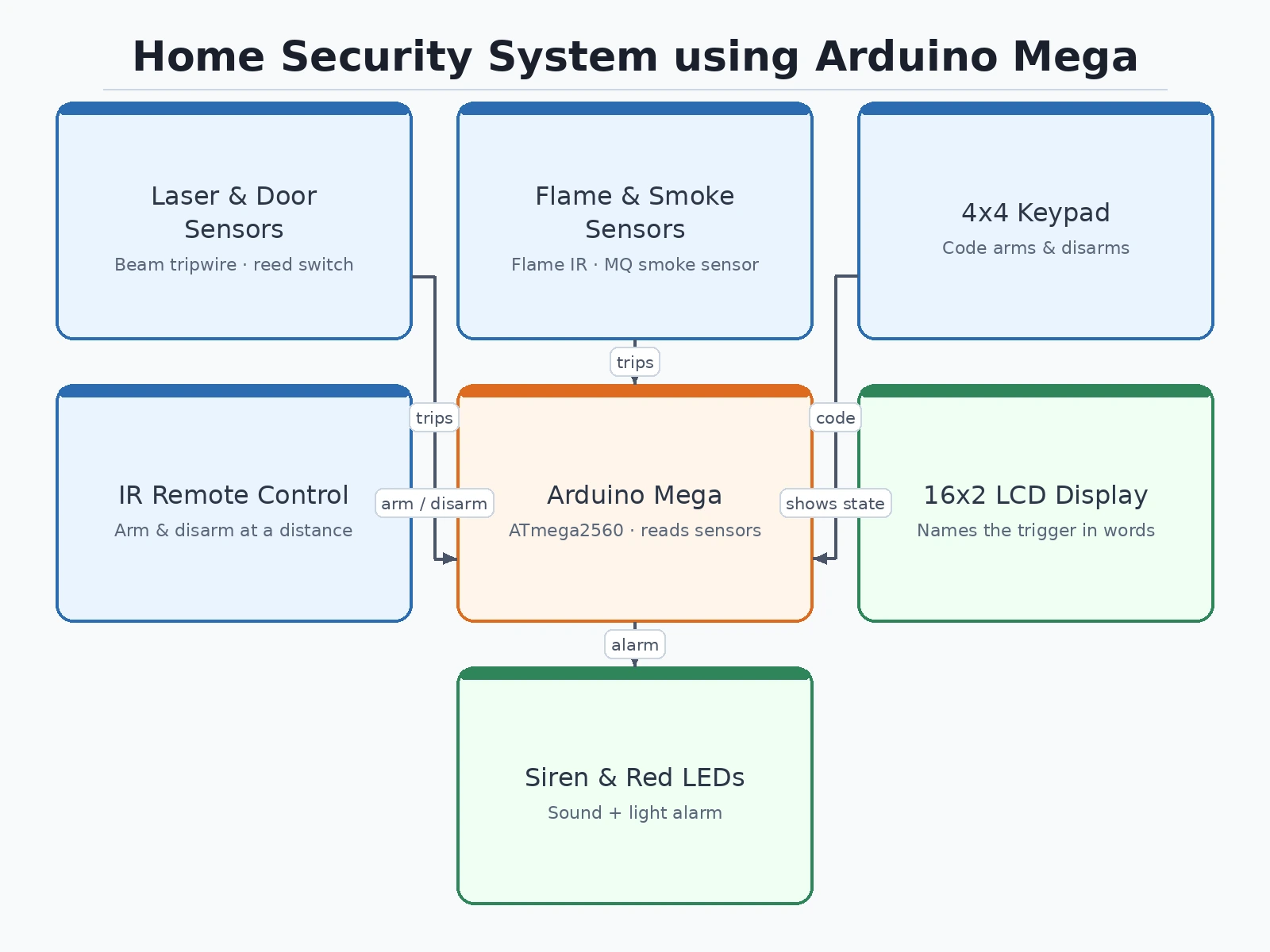
This project starts as a keypad and ends as a warning anyone in the room can understand. An Arduino Mega watches four sensors at once — a laser beam, a magnetic door sensor, a flame sensor and a smoke sensor — and a 16x2 LCD reports what happens in plain words: Alarm On, Laser Interrupted, Flame Spotted, Smoke Detected, System Inactive. A 4x4 keypad arms and disarms the system with a code, an infrared remote does the same from across the room, and a siren sounds with the alarm so the warning is heard as well as seen. The demonstration runs every test on the bench: the code arms the system, a hand breaks the laser beam, the flame sensor trips, the smoke sensor trips, and the code switches the alarm off again.
How it works
From switch-on to a cleared alarm takes six stages a student can trace and test. The builder wires the keypad, the LCD, the laser beam pair, the magnetic door sensor, the flame sensor and the smoke sensor to an Arduino Mega on one board, with an infrared receiver and a siren. The firmware reads the code, arms the system, watches the four sensors, and switches the siren, LEDs and LCD message on when any sensor trips. Each sensor is tested in turn to prove the alarm, then the code is entered to prove the recovery.
- The builder assembles the system: an Arduino Mega, a 4x4 keypad, a 16x2 LCD, a laser beam pair, a magnetic door sensor, a flame sensor, an MQ-series smoke sensor, an infrared receiver and a siren, wired on one board and powered from a 5 V supply.
- The builder checks the keypad and display alone: the LCD asks for a code to start the system, the code is entered, and the display shows Alarm On, so the arming path is known before any sensor logic is added.
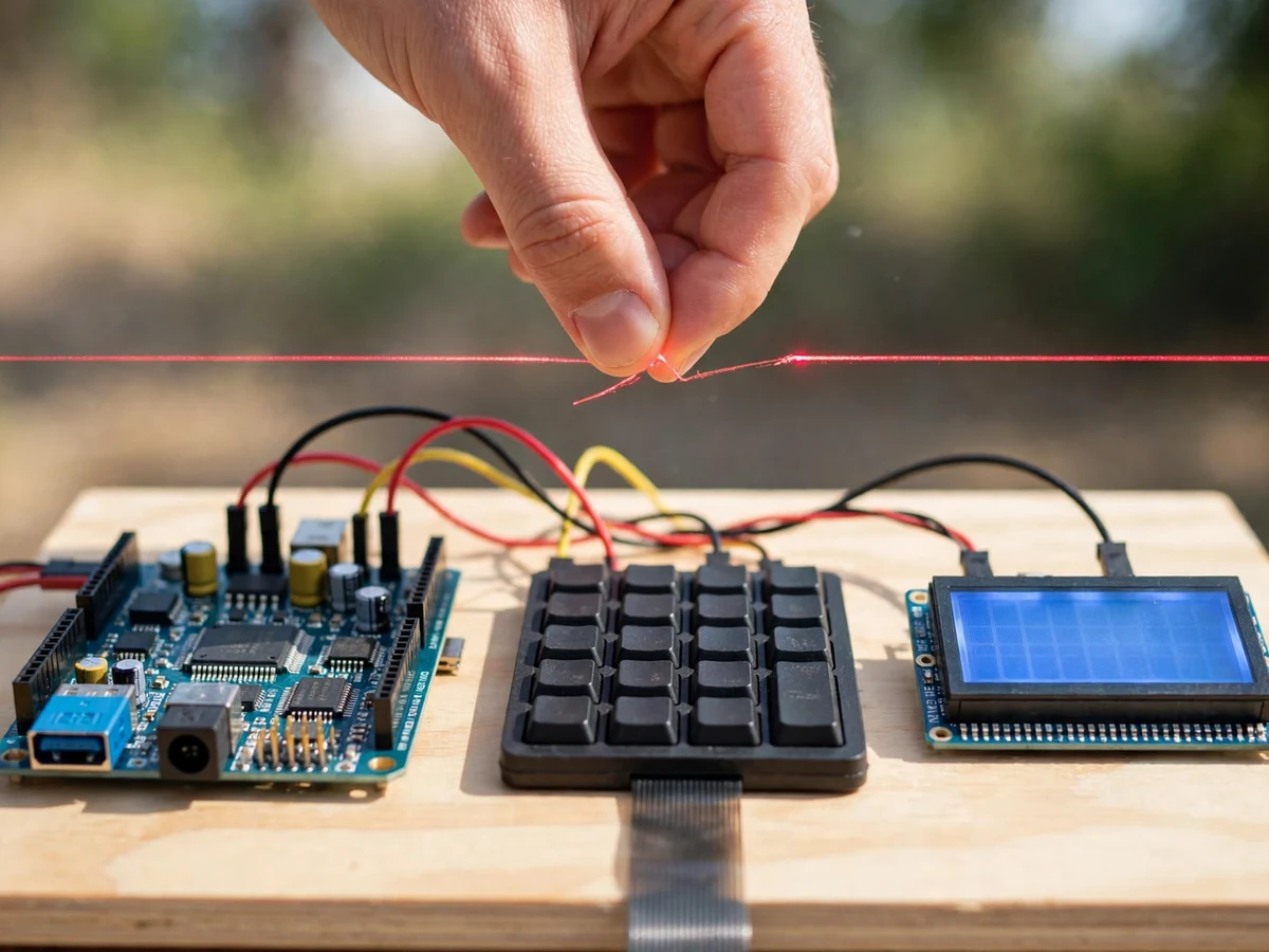
- The builder checks the laser beam: a hand breaks the beam, the display switches to Laser Interrupted, and the siren and red LEDs switch on, so the tripwire is proved.
- The builder checks the flame and smoke sensors in turn: each sensor is triggered, the display names it — Flame Spotted, then Smoke Detected — and the siren and LEDs follow, so every sensor is proved separately.
- The builder checks the remote: the infrared remote arms and disarms the system from across the room, so the second control path is proved.
- The builder records the demonstration run: arming with the code, the laser trip, the flame trip, the smoke trip, the remote control, and the code switching the alarm off with the display back to System Inactive.
Tech stack:
- Arduino Mega · ATmega2560 microcontroller
- 4x4 membrane keypad · code entry
- 16x2 LCD · HD44780 display · I2C backpack
- Laser beam sensor pair · tripwire
- Magnetic door sensor · reed switch pair
- Flame sensor · infrared flame detection
- MQ-series smoke sensor · analogue input
- Infrared remote · arm and disarm
- Siren · alarm output
- Red and green LEDs · alarm indication
- Embedded C · Arduino IDE firmware
| Parameter | Value |
|---|---|
| Controller | Arduino Mega · ATmega2560 · 16 MHz |
| Code entry | 4x4 membrane keypad · arms and disarms with a code |
| Remote control | Infrared remote · arms and disarms from across the room |
| Display | 16x2 LCD · HD44780 · plain-word status messages |
| Laser sensor | Laser beam pair · trips on beam break |
| Door sensor | Magnetic reed-switch pair · trips when the two boxes part |
| Flame sensor | Infrared flame sensor · trips on flame |
| Smoke sensor | MQ-series sensor · analogue input · trips on smoke |
| Alarm outputs | Siren and red LEDs · switch on with the alarm |
| Power | 5 V supply · bench supply |
| Build style | Single-board bench prototype |
Project features
The build works because every trigger ends up as a message a person can act on. The sensors are read continuously, the LCD names the trigger as it happens, and the siren and LEDs follow the alarm state — not a raw sensor value to interpret.
- [Keypad arming and disarming] A 4x4 membrane keypad arms and disarms the system with a code, so the system only changes state for someone who knows the code — implemented in the base build.
- [Plain-word LCD status] The 16x2 LCD shows the system state in plain words — Alarm On, System Inactive, Laser Interrupted, Flame Spotted, Smoke Detected — so anyone in the room can read what happened without a manual — implemented in the base build.
- [Laser beam tripwire] A laser beam across the board trips the alarm the moment a hand breaks it, so an entry across the beam is caught immediately — implemented in the base build.
- [Magnetic door sensor] A magnetic reed-switch pair watches a door: the two boxes part when the door opens and the alarm trips — implemented in the base build.
- [Flame sensor] A flame sensor watches for fire and trips the alarm when it sees one, with the display naming the trigger — implemented in the base build.
- [Smoke sensor] An MQ-series smoke sensor watches the air and trips the alarm on smoke, with the display naming the trigger — implemented in the base build.
- [Infrared remote control] An infrared remote arms and disarms the system from across the room, so the keypad is not the only way in — implemented in the base build.
- [Siren and LED alarm] A siren sounds with the alarm and red LEDs light, so the warning is heard and seen — implemented in the base build.
- [Alarm recovery] The right code switches the alarm off and the display returns to System Inactive, so the system resets itself after a trigger — implemented in the base build.
What is included
- Working board build with Arduino Mega, 4x4 keypad, 16x2 LCD, laser beam pair, magnetic door sensor, flame sensor, MQ-series smoke sensor, infrared remote and siren
- Arduino firmware with the arming, sensor-watch and alarm logic and the plain-word LCD messages
- Wiring diagram and component list
- Test and demonstration procedure (keypad check, laser trip, flame check, smoke check, remote check, recovery check)
- Project report PDF (sensor interfacing, arming logic, demonstration results, honest measurement limits)
- PPT presentation for final review
- Viva Q&A preparation document (how each sensor works, what the LCD messages mean, why the smoke reading is relative and not a PPM figure, what the system cannot detect, what limits the alarm)
Limitations & prerequisites
- Tabletop model, not certified: this is a student prototype for learning and demonstration, not a certified burglar or fire alarm, and it must never be presented as one.
- Local alarm only: the siren and LEDs are local only, with no SMS, call or app alert and no remote monitoring in the base build.
- Line-of-sight laser: the laser beam only guards the line it crosses, so anything that passes above, below or around the beam is not detected.
- Flame sensor sees infrared: the flame sensor responds to infrared sources, so strong sunlight or a bright lamp near the sensor can affect it.
- Relative smoke reading: the smoke sensor gives a relative reading, not a measured concentration in parts per million, so it cannot be quoted as a safety figure.
- Temperature and humidity fitted, not demonstrated: a DHT11 temperature and humidity module sits on the demo board, but the demonstration does not show temperature or humidity readouts, so they are not claimed as features.
- No NFC and no web dashboard: arming is by keypad code or infrared remote only; this build has no NFC tap and no cloud dashboard, unlike the IoT home security model on this site.
Frequently Asked Questions
Is this project suitable for a final-year project?
Yes, for Electronics, Electrical and IoT programmes, because it combines keypad input, four different sensors, LCD messaging and an alarm output on a single microcontroller into one testable loop, with a clear review thread around the arming logic and the sensor triggers.
How does the home security system work?
An Arduino Mega reads a 4x4 keypad, a laser beam pair, a magnetic door sensor, a flame sensor and a smoke sensor. The code arms the system, the 16x2 LCD shows the state in plain words, and when any sensor trips the siren sounds, the red LEDs light and the display names the trigger.
What does the demonstration show?
Arming with the code, a hand breaking the laser beam with the display reporting Laser Interrupted, the flame sensor tripping with Flame Spotted, the smoke sensor tripping with Smoke Detected, the infrared remote arming and disarming the system, and the code switching the alarm off with the display back to System Inactive.
How is this different from the IoT home security model on this site?
That build runs on an Arduino Yun with ultrasonic, vibration, gas and water sensors, NFC arming and a web dashboard. This build runs on an Arduino Mega with a keypad, a laser beam, a magnetic door sensor, a flame sensor and a smoke sensor, armed by code or infrared remote, with no cloud dashboard.
What will I receive with the project?
The working board build with Arduino Mega, keypad, LCD, four sensors, infrared remote and siren, the firmware with the arming and alarm logic, the wiring diagram and component list, the test and demonstration procedure, the project report, the presentation and the viva Q&A document. A 5 V supply and a laptop for uploading the firmware are needed, both covered in the setup guide.
Components & software requirements
- Arduino Mega · ATmega2560 microcontroller
- 4x4 membrane keypad · code entry
- 16x2 LCD · HD44780 display · I2C backpack
- Laser beam sensor pair · tripwire
- Magnetic door sensor · reed switch pair
- Flame sensor · infrared flame detection
- MQ-series smoke sensor · analogue input
- Infrared remote · arm and disarm
- Siren · alarm output
- Red and green LEDs · alarm indication
- Embedded C · Arduino IDE firmware
Delivery information
Built-to-order project. Delivery timeline is shared after order confirmation based on current queue.
Support terms
Complete documentation, setup guide, and viva preparation included. Support for setup and explanation provided.
Download free synopsis (PDF)
Enter your name and WhatsApp number — the synopsis PDF downloads immediately. We may send occasional project updates on WhatsApp; no spam.