
More project photos (2)

Watch it work
The problem
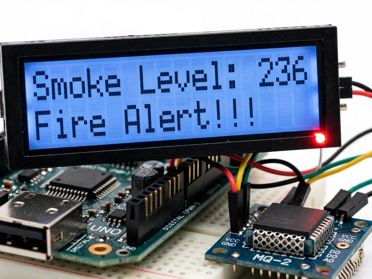
This project starts as a sensor reading and ends as a warning anyone in the room can understand. An MQ-2 smoke sensor watches the air, an Arduino Uno reads it, and a 16x2 LCD shows the live smoke level with a plain-language message: Normal while the air is clear, Fire Alert when the level crosses the threshold. A red LED and a buzzer switch on with the alert, so the warning is seen and heard. The demonstration runs the full cycle on the bench: clean air reading in the eighties, smoke from a lit mosquito coil driving the level to 236 with the alarm on, and the level falling back into the nineties as the smoke clears.
How it works
From switch-on to a cleared alarm takes five stages a student can trace and test. The builder wires the MQ-2 sensor, the 16x2 LCD, the red LED and the buzzer to an Arduino Uno in an enclosure. The firmware reads the sensor, shows the level on the LCD, and switches the LED, buzzer and message on when the level crosses the threshold. Smoke from a coil is brought near the sensor to prove the alarm, then removed to prove the recovery.
- The builder assembles the system: an MQ-2 smoke sensor, a 16x2 LCD, a red LED and a buzzer, wired to an Arduino Uno in a simple enclosure, powered from a 5 V USB supply.
- The builder checks the sensor alone: the MQ-2 is powered and left to warm up, and its reading in clean air is recorded, so the normal baseline is known before any alarm logic is added.
- The builder checks the display alone: the LCD shows the live level and the Normal message, and the reading is watched as the sensor is warmed, so a stuck or reversed reading is found early.
- The builder checks the alarm: smoke from a lit mosquito coil is brought near the sensor, the level is watched as it climbs past the threshold, and the red LED, the buzzer and the Fire Alert message are checked together.
- The builder records the demonstration run: clean air in the eighties, the climb to 236 with the alarm on, and the fall back into the nineties with the alarm off, all visible in the video.
Tech stack:
- Arduino Uno · ATmega328P microcontroller
- MQ-2 smoke sensor · tin-dioxide element
- 16x2 LCD · HD44780 display
- Red LED alarm · digital output
- Buzzer alarm · digital output
- Threshold alarm logic · firmware comparison
- Enclosure build · handmade housing
- Embedded C · Arduino IDE firmware
| Parameter | Value |
|---|---|
| Controller | Arduino Uno · ATmega328P · 16 MHz |
| Smoke sensor | MQ-2 · tin-dioxide gas sensor · analogue input |
| Display | 16x2 LCD · HD44780 · smoke level and Normal/Fire Alert messages |
| Alarm outputs | Red LED and buzzer · switch on above the threshold |
| Alarm threshold | Fixed threshold in the demo build · level 236 demonstrated at peak |
| Demo smoke source | Lit mosquito coil · level rises from the eighties to 236 |
| Power | 5 V USB · bench supply |
| Build style | Handmade enclosure prototype |
Project features
The build works because every reading ends up as a message a person can act on. The MQ-2 sensor is read continuously, the level is shown on the LCD as it changes, and the alarm state follows the threshold — not a raw number to interpret.
- [Live smoke level on the LCD] The MQ-2 reading is shown on the 16x2 LCD as it changes, so the smoke level is readable at a glance — implemented in the base build.
- [Normal message in clean air] Clean air reads in the eighties and the display says Normal, so a safe room is confirmed rather than assumed — implemented in the base build.
- [Fire Alert message on smoke] Smoke drives the reading past the threshold and the display switches to Fire Alert, so the danger state is named in plain words — implemented in the base build.
- [Red LED alarm] A red LED lights with the alert, so the warning is visible from across the room — implemented in the base build.
- [Buzzer alarm] A buzzer sounds with the alert, so the warning is heard even when nobody is looking at the display — implemented in the base build.
- [Alarm recovery] When the smoke clears, the level falls back below the threshold and the LED, buzzer and alert switch off, so the detector resets itself — implemented in the base build.
- [Enclosure build] The Arduino, sensor, LCD, LED and buzzer sit in a simple handmade enclosure with the display and LED on the front, so the reading and the alarm state are visible at all times — implemented in the base build.
What is included
- Working enclosure build with Arduino Uno, MQ-2 smoke sensor, 16x2 LCD, red LED and buzzer
- Arduino firmware with the threshold alarm logic and the Normal/Fire Alert messages
- Wiring diagram and component list
- Test and demonstration procedure (sensor warm-up, clean-air baseline, alarm check, recovery check)
- Project report PDF (MQ-2 sensing, threshold logic, demonstration results, honest measurement limits)
- PPT presentation for final review
- Viva Q&A preparation document (how the MQ-2 sensor works, what the threshold means, why the level is a relative reading and not a PPM figure, what the sensor cannot identify, what limits the alarm)
Limitations & prerequisites
- Uncalibrated relative reading: the smoke level is a relative reading from the MQ-2, not a measured concentration in parts per million, so it cannot be quoted as a safety figure.
- Fixed threshold: the alarm threshold is fixed in the demo build, with no adjustable setpoint in the base build.
- Cannot identify the gas: the MQ-2 responds to smoke and to other gases such as LPG, so it cannot say what it is sensing.
- Warm-up needed: the MQ-2 needs a warm-up period after power-on before its readings settle.
- Local alarm only: the buzzer and LED are local only, with no SMS or app alert and no remote monitoring in the base build.
- Tabletop model, not certified: this is a student prototype for learning and demonstration, not a certified fire alarm, and it must never be presented as one.
Frequently Asked Questions
Is this project suitable for a final-year project?
Yes, for Electronics, Electrical and IoT programmes, because it combines gas sensing, ADC conversion, threshold logic and a local alarm on a single microcontroller into one testable loop, with a clear review thread around the smoke level and the alarm threshold.
How does the smoke detector work?
The MQ-2 sensor changes resistance as smoke concentration rises. The Arduino reads that change, shows the smoke level on the 16x2 LCD, and switches on a red LED and a buzzer with a Fire Alert message when the level crosses the threshold.
What does the demonstration show?
Clean air reading in the eighties with a Normal message, smoke from a lit mosquito coil driving the reading to 236 with the Fire Alert message, red LED and buzzer on, and the reading falling back into the nineties with the alarm off as the smoke clears.
Is the reading in PPM?
No. The smoke level is an uncalibrated relative reading from the MQ-2, not a measured concentration in parts per million, so it must never be quoted as a safety figure.
What will I receive with the project?
The working enclosure build with Arduino Uno, MQ-2 smoke sensor, 16x2 LCD, red LED and buzzer, the firmware with the threshold alarm logic, the wiring diagram and component list, the test and demonstration procedure, the project report, the presentation and the viva Q&A document. A 5 V USB supply and a laptop for uploading the firmware are needed, both covered in the setup guide.
Components & software requirements
- Arduino Uno · ATmega328P microcontroller
- MQ-2 smoke sensor · tin-dioxide element
- 16x2 LCD · HD44780 display
- Red LED alarm · digital output
- Buzzer alarm · digital output
- Threshold alarm logic · firmware comparison
- Enclosure build · handmade housing
- Embedded C · Arduino IDE firmware
Delivery information
Built-to-order project. Delivery timeline is shared after order confirmation based on current queue.
Support terms
Complete documentation, setup guide, and viva preparation included. Support for setup and explanation provided.
Download free synopsis (PDF)
Enter your name and WhatsApp number — the synopsis PDF downloads immediately. We may send occasional project updates on WhatsApp; no spam.