
More project photos (2)
The problem
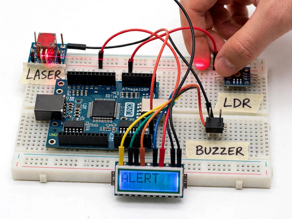
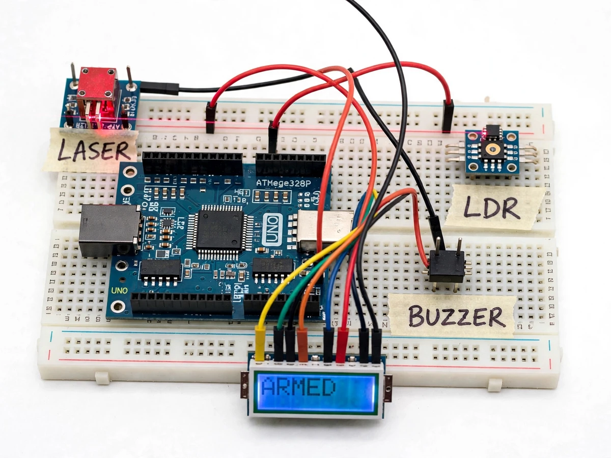
A laser tripwire security alarm guards a doorway or boundary with a line of light instead of a lock or a camera. The Laser Tripwire Security Alarm System using LDR places a small red laser module on one side of a passage and a light-dependent resistor (LDR) sensor on the other, so the beam falls on the sensor continuously while the passage is clear. When a person or object crosses the passage, the beam is broken, the light on the sensor vanishes, and the Arduino controller sounds a buzzer, lights a red alert LED, and switches the LCD display from ARMED to ALERT. The alarm keeps sounding until the reset button is pressed, so a momentary crossing cannot silence itself unnoticed. The answer to an unguarded doorway is therefore a low-cost, always-on light beam that turns any crossing into an immediate local alarm, with no camera, no recording, and no network connection required.
Rooms, labs, storerooms and small shops often have a doorway that is watched only when someone happens to be nearby, and a simple door sensor can be defeated by leaving a door open or by entering through an unguarded gap. A beam stretched across the passage itself closes that gap: anything crossing the line must break the beam, regardless of whether a door is open or shut. The beam is invisible in normal use except for the small red spot on the sensor housing, and the whole unit runs from a USB supply or a battery pack, so it can be set up on a table, a doorway frame or a lab bench for demonstration.
Builder note from the build: the LDR threshold must be trimmed with the potentiometer after mounting, not set once on the bench. Room light falling on the sensor raises its baseline reading, so the threshold is set in the actual mounting position with the laser on, midway between the laser-lit reading and the beam-broken reading; a short opaque tube around the LDR shields it from overhead light and is the main fix for false triggers in bright rooms.
650 nm red laser module shines a narrow beam across the passage.
Follow the working sequence
How it works
The Laser Tripwire Security Alarm System using LDR works as one continuous chain from light to alarm. A 650 nm red laser module shines a narrow beam across a doorway onto an LDR sensor, and the LDR resistance collapses under the laser spot, holding the sensor voltage at its lit level. The Arduino Uno reads that voltage continuously through its analog input and compares it with the threshold set by the trim potentiometer. While the beam is intact the reading stays on the lit side of the threshold and the LCD shows ARMED with the buzzer silent. When a person or object breaks the beam, the LDR resistance rises sharply, the sensor voltage crosses the threshold, and the Arduino latches the alarm: the buzzer sounds, the red LED lights, and the LCD switches to ALERT. The alarm stays latched until the reset button is pressed, after which the system re-arms itself once the beam is restored.
- The 650 nm laser module is powered and aimed across the passage so its spot falls on the LDR sensor housed in its shielding tube.
- The LDR and its fixed resistor form a voltage divider, and the Arduino reads the divider voltage on an analog pin several times per second.
- The trim potentiometer sets the threshold midway between the laser-lit reading and the beam-broken reading, adjusted in the final mounting position.
- While the beam is intact, the reading stays on the lit side of the threshold, the LCD shows ARMED, and the buzzer and LED stay off.
- When a crossing breaks the beam, the LDR resistance rises, the divider voltage crosses the threshold, and the Arduino registers a trip.
- The firmware latches the alarm state: the buzzer sounds continuously, the red LED lights, and the LCD switches to ALERT.
- Pressing the reset button clears the latch, and the system returns to ARMED once the beam is restored on the sensor.
Tech stack:
- Arduino Uno (ATmega328P)
- LDR sensor module · GL5528 class
- 650 nm red laser module
- 16x2 character LCD
- Active buzzer · red LED
- 10 kΩ trim potentiometer
- Arduino IDE · C/C++ firmware
- Breadboard · jumper wires · mounting stands
| Parameter | Value |
|---|---|
| Controller | Arduino Uno · ATmega328P · 5 V logic (datasheet value) |
| Laser module | 650 nm red dot module · 5 V supply (datasheet value) |
| Light sensor | GL5528 class LDR · dark resistance approximately 1 MΩ · light resistance approximately 10–20 kΩ (datasheet values) |
| Sensing principle | Laser beam on LDR · voltage divider to Arduino analog input |
| Detection span | Design target: up to approximately 3 m across a doorway (buyer-verified by alignment test) |
| Response | Design target: alarm latches within approximately 1 second of beam break |
| Alarm output | Active buzzer · 5 V · continuous tone until manual reset |
| Display | 16x2 character LCD · ARMED / ALERT states · red alert LED |
| Power | 5 V USB supply or 9 V battery pack (design choice) |
| Reset | Push-button manual reset · system re-arms when beam is restored |
Project features
The Laser Tripwire Security Alarm System using LDR combines four capabilities that make a doorway beam practical rather than just a bench demo: instant beam-break detection that reacts the moment the laser spot leaves the sensor, a latched alarm that keeps sounding until a person deliberately resets it, a clear ARMED/ALERT display on the LCD with a matching red LED, and a threshold trim plus a shielded sensor housing that keeps ordinary room light from tripping the alarm. Around that core, the build adds a compact breadboard layout with labelled modules, simple doorway mounting on two small stands, and an optional relay output for an external siren or lamp on request. Each capability below is part of the base build unless it is explicitly marked optional or future scope. All of it is demonstrated live by walking through the beam.
- [Beam-Break Intrusion Detection] The red laser beam falls on the LDR continuously, and any person or object crossing the passage breaks the beam and triggers the alarm. Detection needs no motion sensor and no camera, and it works in daylight and in darkness because the beam itself is the sensed signal.
- [Latched Alarm with Manual Reset] Once triggered, the buzzer and red LED stay on until the reset button is pressed. A quick crossing therefore cannot sound a brief chirp and fall silent before anyone notices, which is the behaviour a security alarm must have.
- [ARMED/ALERT LCD Status] A 16x2 LCD shows ARMED while the beam is intact and switches to ALERT on a break, with a red LED mirroring the state. The status is readable from across a room, and it makes the demo self-explanatory without a laptop connected.
- [Adjustable Sensitivity Trim] A potentiometer sets the light threshold that separates the laser-lit reading from the beam-broken reading. The trim is adjusted in the actual mounting position after installation, so the alarm suits both dim rooms and bright labs.
- [Ambient-Light Shielded Sensor] The LDR sits inside a short opaque tube that admits the laser spot while blocking overhead room light. This shielding, together with the threshold trim, is what keeps a sunny room or a switched-on tube light from causing false alarms.
- [Simple Doorway Mounting] The laser module and the sensor mount on two small stands that sit on either side of a doorway or passage, aligned by the visible red spot. Alignment takes minutes with no tools beyond the stands, and the stands fold away for transport to a review.
- [Optional Relay Output] Optional customization, not in the base build: a relay module can switch an external siren, lamp or mains-rated alert device on request. The base build alarms locally with its own buzzer and LED only.
Future scope, not included in the base build: SMS or GSM alert on trip, multiple crossed beams for a wider passage, and event logging with timestamps.
What is included
- Working laser tripwire prototype (Arduino, laser module, LDR sensor, buzzer, LED, LCD, stands)
- Arduino firmware source code with threshold and latch logic commented
- Circuit and wiring diagram for the complete build
- Threshold-setting and alignment procedure for the buyer's own room
- Project report PDF (background, LDR theory, circuit design, methodology, results template)
- PPT presentation for final review
- Viva Q&A preparation document (LDR characteristics, voltage divider, threshold logic, latching)
Limitations & prerequisites
- The beam guards a single line across a passage, not a whole room — anything passing above, below or around the beam is not detected.
- Detection span is a design target of approximately 3 m; longer spans need careful alignment and a darker sensor housing, verified by the buyer's own alignment test.
- Strong direct sunlight falling straight into the sensor tube can still raise the baseline reading, so the sensor must face away from windows and the threshold must be re-trimmed on site.
- The base build alarms locally only — no SMS, call or app notification is included; GSM alert is an optional extension.
- The prototype is an academic demonstration build, not a certified security system, and it must not be presented as burglary protection for real premises.
- The laser module is a low-power 650 nm class device; the beam must never be aimed at eyes, and alignment is done using the spot on the sensor housing, not by looking into the beam.
- Battery runtime depends on the pack used and on how long the alarm sounds; the design assumes USB mains power for continuous duty.
Frequently Asked Questions
Is this project suitable for a final-year project?
Yes, the Laser Tripwire Security Alarm System using LDR suits Electronics, Electrical and IoT & Embedded final-year work because it combines sensor physics, analog interfacing, threshold logic and a complete working prototype in one demonstrable build. The report covers LDR characteristics, the voltage-divider circuit, threshold calibration and latching alarm logic, all of which are standard viva topics for these branches.
Which controller is used and why?
The Arduino Uno (ATmega328P) is used because the whole system needs only one analog input, a few digital outputs and simple threshold logic, all of which the Uno provides with 5 V logic. The firmware reads the LDR divider voltage, compares it with the potentiometer-set threshold, drives the buzzer, LED and LCD, and holds the latched alarm state until reset.
Will room light or sunlight cause false alarms?
No, not when the sensor is installed as instructed, because the LDR sits inside a short opaque shielding tube and the threshold is trimmed in the actual mounting position between the laser-lit and beam-broken readings. Direct sunlight aimed straight into the tube is the one case that can still raise the baseline, so the sensor must face away from windows and the threshold must be re-trimmed after any move.
What power supply does it need?
The prototype runs from a standard 5 V USB supply for continuous use, or from a 9 V battery pack for portable demonstration, because the Arduino, laser module, LCD and buzzer all operate from the board's 5 V rail. For a full-day exhibition or a review, USB mains power is recommended, since battery runtime falls the longer the buzzer sounds during alarm tests.
Can a GSM alert or a second beam be added?
Yes, both are realistic customizations developed on request, because the firmware already exposes a latched trip signal that a GSM module or a relay can act on. A GSM module can send an SMS on trip, a second beam can guard a wider passage, and a relay output can switch an external siren or lamp; none of these are in the base build, so they are quoted as extensions.
What will I receive with the project?
The complete kit includes the working prototype with its mounting stands, the commented Arduino firmware, the circuit and wiring diagram, the threshold-setting and alignment procedure, the project report PDF, the review PPT and the viva Q&A document. The buyer sets the threshold in their own room using the included procedure, so the calibration values in the report are the buyer's own readings, not invented figures.
Components & software requirements
- Arduino Uno (ATmega328P)
- LDR sensor module · GL5528 class
- 650 nm red laser module
- 16x2 character LCD
- Active buzzer · red LED
- 10 kΩ trim potentiometer
- Arduino IDE · C/C++ firmware
- Breadboard · jumper wires · mounting stands
Delivery information
Built-to-order project. Delivery timeline is shared after order confirmation based on current queue.
Support terms
Complete documentation, setup guide, and viva preparation included. Support for setup and explanation provided.
Download free synopsis (PDF)
Enter your name and WhatsApp number — the synopsis PDF downloads immediately. We may send occasional project updates on WhatsApp; no spam.