
More project photos (2)
The problem
Pulse oximeters and heart-rate monitors are among the most-requested biomedical electronics projects because the sensing principle is genuinely interesting: blood absorbs red and infrared light differently depending on oxygenation, and the pulsing component of that absorption tracks the heartbeat. Most students, however, only wire a sensor to a display and read a library value, never learning what photoplethysmography (PPG) actually is, why two wavelengths are needed, or where the readings can go wrong. This project closes that gap: the Arduino polls the MAX30100 over I2C, the firmware filters the raw red and IR samples with a moving average, beats are detected from the IR waveform, and SpO2 is estimated from the ratio-of-ratios of the two channels. Results appear live on a 0.96-inch OLED, and a buzzer alerts when BPM or SpO2 leave the configured band. Because this is a module-level prototype, its limits are stated plainly: it is not a medical device, it is not calibrated against a clinical oximeter, and the report documents a verification procedure the buyer runs against a commercial device so every comparison reading is honestly their own.
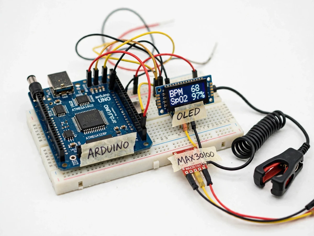
Placed in the clip probe so the sensor window sits against the finger pad.
Follow the working sequence
How it works
- The fingertip is placed in the clip probe so the MAX30100 window sits against the finger pad; the clip's light shield blocks ambient light from the photodiode.
- The MAX30100 alternately fires its red (660 nm) and IR (880 nm) LEDs; the on-chip photodiode and 16-bit ADC convert the reflected light into digital samples stored in the sensor's FIFO.
- The Arduino polls the FIFO over I2C (100 kHz bus) at roughly 100 samples per second (design target), reading interleaved red and IR sample streams.
- Firmware applies a moving-average filter to both channels, removes the slow DC baseline, and detects beats from peaks in the IR AC waveform; BPM is 60 divided by the average inter-beat interval over the design window.
- SpO2 is estimated from the ratio-of-ratios: (AC_red / DC_red) divided by (AC_ir / DC_ir), mapped to a percentage through an empirical lookup calibrated for the module (displayed range 70–100%, design target).
- The OLED redraws BPM, SpO2 and a heartbeat glyph about once per second (design target); if BPM is outside the configured band or SpO2 is below threshold, the buzzer sounds and the display flags the value.
- For the report, the buyer runs the included verification procedure: paired readings against a commercial finger oximeter on 3–5 volunteers, noting the observed deviation — the report documents these student-measured values, not vendor claims.
Tech stack:
- Arduino Uno · Nano (ATmega328P)
- MAX30100 pulse-oximeter sensor module
- 0.96-inch SSD1306 OLED (I2C)
- Arduino IDE, C/C++ firmware
- I2C bus, 100 kHz sensor polling
- Moving-average PPG filtering
- Piezo buzzer alarm logic
- Breadboard wiring + finger-probe clip
| Parameter | Value |
|---|---|
| Controller | Arduino Uno/Nano (ATmega328P, 16 MHz) |
| Sensor | MAX30100, red 660 nm + IR 880 nm LEDs, I2C |
| Sampling | Approximately 100 samples/s (design target) |
| Display | 0.96-inch 128×64 SSD1306 OLED, I2C |
| Display refresh | Approximately 1 s (design target) |
| BPM display range | 30–200 BPM (design target range) |
| SpO2 display range | 70–100% (design target range) |
| Signal filter | Moving average over 4 beats (design) |
| Alert band | Below 50 / above 120 BPM, SpO2 below 92% (configurable) |
| Power | 5 V via USB or adapter, approximately 120 mA (expected) |
| Accuracy | Indicative only — not calibrated against a clinical oximeter; verified by the buyer against a commercial device |
Project features
- [MAX30100 dual-wavelength PPG sensing] A MAX30100 module shines red (660 nm) and infrared (880 nm) LEDs into the fingertip and digitizes the reflected light — the pulsatile AC component of each channel is the photoplethysmograph that carries the heartbeat.
- [Live BPM and SpO2 on OLED] The 0.96-inch SSD1306 OLED renders BPM and SpO2 side by side with a live heartbeat indicator, refreshed about once per second so the display visibly tracks the finger on the probe.
- [Moving-average filter in firmware] Raw samples pass through a moving-average stage (4-beat design window) before beat detection, which visibly steadies the display against small hand tremor and power-line ripple.
- [Buzzer alert band] A piezo buzzer sounds for about 3 seconds when BPM leaves the configured band (below 50 or above 120 by default) or SpO2 drops below the threshold, demonstrating a simple clinical-style alarm chain.
- [Finger-probe clip assembly] The sensor is mounted in a spring-loaded finger clip with a light shield around the module, teaching the mechanical side of optical sensing: stable pressure and blocked ambient light.
- [Buyer-run verification procedure] A step-by-step comparison protocol against a commercial finger oximeter is included — the buyer records paired readings and reports the observed deviation honestly in their own report.
- [Serial telemetry for the viva] BPM and SpO2 values also stream over USB serial, so the student can plot the PPG waveform and ratio values on a laptop during demonstration and viva.
What is included
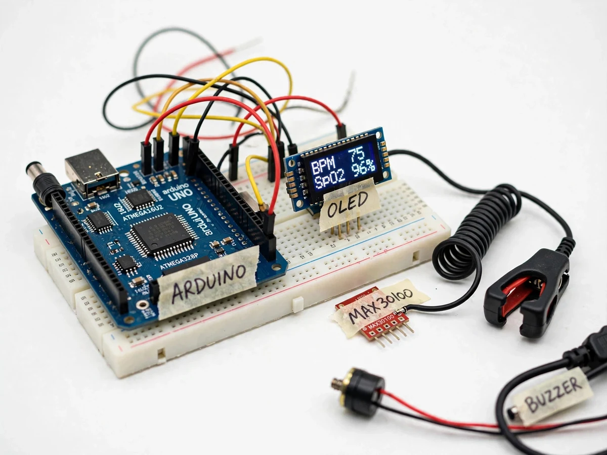
- Assembled and tested prototype (Arduino, MAX30100 module in finger-probe clip, OLED, buzzer, breadboard wiring)
- Arduino firmware source (C/C++) with commented filtering, beat detection and alert logic
- Wiring diagram and sensor placement / finger-probe positioning guide
- Calibration and verification procedure the buyer runs against a commercial finger oximeter
- Project report PDF (PPG principle, MAX30100, firmware design, verification results template)
- PPT presentation for final review
- Viva Q&A preparation document (photoplethysmography, ratio-of-ratios, I2C, noise sources and limits)
Limitations & prerequisites
- This is an educational prototype, not a medical device — readings are indicative and must not be used for diagnosis or health decisions.
- The build is not calibrated against a clinical oximeter; comparison against a commercial device is a buyer-run procedure, not a factory certification.
- Motion artifacts are the main error source: any finger movement during measurement corrupts both BPM and SpO2, typically for several seconds after the movement stops.
- Ambient light leaking into the probe shifts the photodiode baseline; readings need the clip's light shield seated and a shaded measurement position.
- Cold fingers, nail polish, thick calloused skin and heavy or light probe pressure all shift readings; the report documents this as measured behavior.
- No ECG reference channel exists at this module level, so beat detection relies on the PPG waveform alone and cannot distinguish arrhythmias.
Frequently Asked Questions
How does the MAX30100 measure heart rate and SpO2?
The sensor shines red (660 nm) and infrared (880 nm) light into the finger and digitizes the reflection. The pulsing part of the infrared signal tracks blood-volume changes with each heartbeat (that is the BPM source), and oxygenated blood absorbs the two wavelengths differently, so the ratio of the two channels maps to an SpO2 estimate.
Is this a medical-grade device?
No. It is an educational prototype built from a hobby sensor module. Readings are indicative, not calibrated against a clinical oximeter, and must never be used for health decisions. The verification procedure included with the build exists precisely so the student reports what the device actually achieves.
Why do the readings jump when I move my finger?
Motion changes the optical path between the LEDs, the blood volume under the sensor and the ambient-light leakage all at once — the PPG waveform degrades and both BPM and SpO2 estimates destabilize. Clinical devices handle this with much heavier processing; this prototype's honest answer is to hold still during measurement.
How is the build verified?
With the included buyer-run procedure: paired readings against a commercial finger oximeter on 3–5 volunteers, recorded in a comparison table the student fills in and discusses in the report. The report template documents the observed deviation rather than claiming a pre-built accuracy figure.
Is this project suitable for a final-year project?
Yes — for Electronics, E&TC and IoT programs. It demonstrates optical sensing, I2C interfacing, embedded signal filtering and honest experimental verification, which together make a strong biomedical-electronics viva. Suitable for B.E./B.Tech final-year projects in Electronics, E&TC and IoT.
Components & software requirements
- Arduino Uno · Nano (ATmega328P)
- MAX30100 pulse-oximeter sensor module
- 0.96-inch SSD1306 OLED (I2C)
- Arduino IDE, C/C++ firmware
- I2C bus, 100 kHz sensor polling
- Moving-average PPG filtering
- Piezo buzzer alarm logic
- Breadboard wiring + finger-probe clip
Delivery information
Built-to-order project. Delivery timeline is shared after order confirmation based on current queue.
Support terms
Complete documentation, setup guide, and viva preparation included. Support for setup and explanation provided.
Download free synopsis (PDF)
Enter your name and email — the synopsis PDF downloads immediately. We may send occasional project updates; no spam, unsubscribe anytime.