
More project photos (3)
The problem
Thermal cameras are standard tools for finding hotspots in electrical panels, checking overheating components, and spotting heat leaks in buildings — but commercial imagers cost far more than a student budget allows, so most electronics students never handle the technology behind them. A low-resolution infrared array like the MLX90640 changes that: 768 thermopile pixels return real surface-temperature data over I2C, and a microcontroller can turn that sparse grid into a readable thermal image with interpolation and a colour map. This project packages those ideas into a handheld, battery-powered camera with its own display, so the entire signal chain — IR sensing, per-pixel temperature conversion, image upscaling, and live rendering — lives in one device the student can hold, open, and explain. It makes a strong project build because every stage is inspectable: the sensor datasheet, the I2C transactions, the interpolation maths, and the display driver all live in the firmware.
32x24 far-infrared thermopile array measures infrared radiation across 768 pixels; each pixel maps a surface temperature.
Follow the working sequence
How it works
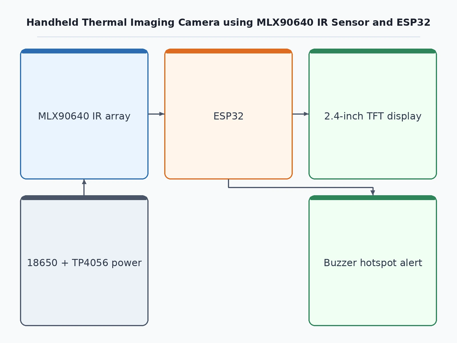
- The MLX90640 measures infrared radiation across its 32x24 thermopile pixel grid; each pixel's reading depends on the surface temperature in its field of view.
- The ESP32 polls the sensor over I2C (address 0x33, fast mode up to 1 MHz) at the configured refresh rate and pulls the raw pixel frame plus ambient and supply readings.
- Firmware applies the factory calibration constants stored in the sensor's EEPROM to convert every raw pixel value into a surface temperature in degrees Celsius.
- The 32x24 temperature grid is upscaled to 320x240 by bilinear interpolation, smoothing the coarse native pixels into a continuous image.
- Each interpolated temperature is mapped through a colour lookup table (ironbow by default) into RGB values for the display.
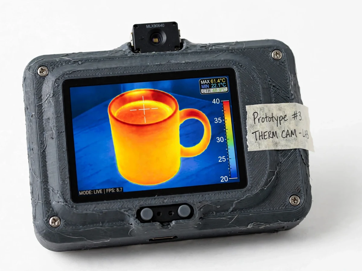
- The frame is drawn on the 2.4-inch SPI TFT with the temperature scale bar, min/max/center-spot readouts and the hotspot crosshair overlaid.
- The two buttons switch colour palettes or toggle the hotspot alert threshold, and the battery/charging module keeps the unit running away from a bench supply.
Tech stack:
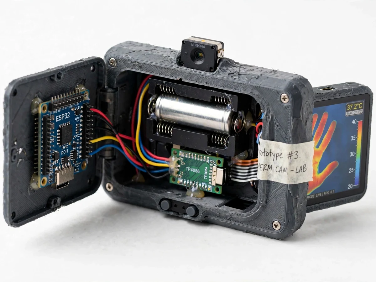
- ESP32 (dual-core SoC, Arduino framework)
- MLX90640 32x24 far-infrared array sensor
- 2.4-inch TFT LCD, 320x240, SPI (ILI9341 driver)
- I2C sensor interface (fast mode up to 1 MHz)
- 18650 Li-ion cell · TP4056 charging module
- TFT_eSPI graphics library
- Arduino IDE toolchain
| Parameter | Value |
|---|---|
| IR sensor | MLX90640, 32x24 pixels (768 FIR pixels, factory-calibrated) |
| Field of view | 110 x 75 degrees or 55 x 35 degrees (module variant, datasheet) |
| Sensor interface | I2C, address 0x33, up to 1 MHz fast mode (datasheet) |
| Refresh rate | 0.5 to 64 Hz programmable (datasheet); firmware uses approximately 8 Hz (design target) |
| Displayed image | 320x240 via bilinear interpolation (design target) |
| Target temperature range | -40 to 300 C (datasheet) |
| Temperature accuracy | ±1 C typical (datasheet value, factory conditions) |
| NETD | 0.1 K RMS at 1 Hz refresh (datasheet) |
| Sensor supply | 3.3 V, under 23 mA (datasheet) |
| Display | 2.4-inch TFT, 320x240 pixels, SPI |
| Battery | Single 18650 Li-ion cell (approximately 2600 mAh) |
| Runtime | Approximately 3-5 hours per charge (component-dependent, design target) |
| Enclosure | 3D-printed PLA handheld housing (approximate 120 x 85 x 45 mm, design target) |
| Controls | 2 tactile buttons, USB-C charging port, onboard buzzer |
Project features
- [Live thermal imaging on TFT] The ESP32 reads all 768 pixels over I2C, converts them to surface temperatures, upscales the 32x24 grid to 320x240 with bilinear interpolation, and renders a live ironbow thermal image on the 2.4-inch display.
- [Spot temperature readouts] The frame overlay shows maximum, minimum and center-spot temperatures with a crosshair marker on the hottest pixel, plus a vertical temperature scale bar for quick reading.
- [Two sensor field-of-view options] The build can use the 110x75 degree wide-angle module for near scenes or the 55x35 degree narrow module for distant targets — chosen at build time.
- [Selectable colour palettes] A push button cycles through ironbow, rainbow and grayscale palettes without reflashing, so the student can compare how palettes change thermal interpretation.
- [Hotspot alert] A configurable temperature threshold triggers the onboard buzzer when any pixel crosses it, demonstrating simple threshold-based detection on real sensor data.
- [Battery-powered handheld operation] A single 18650 Li-ion cell with a TP4056 charging module runs the unit portably; charging happens over USB-C with the cell in place.
- [Factory-calibrated sensing] The MLX90640 ships factory-calibrated with its constants in onboard EEPROM, so no user calibration routine is needed — the firmware applies the datasheet conversion directly.
What is included
- Working handheld thermal camera prototype (enclosure, MLX90640 module, ESP32, TFT, battery, charger)
- Complete ESP32 firmware source code (Arduino framework)
- Wiring diagram and full component list with sourcing notes
- Enclosure 3D-print files (STL) and assembly guide
- Interpolation and colour-mapping explanation notes
- Project report PDF (background, IR thermometry theory, methodology, results discussion)
- PPT presentation for final review
- Viva Q&A preparation document (I2C/SPI, thermopiles, interpolation, emissivity)
Limitations & prerequisites
- The 32x24 native grid is coarse: interpolation smooths the image but cannot create detail that the raw pixels never captured — this is not a FLIR-class imager.
- The ±1 C accuracy is a datasheet-typical value at factory conditions; real readings shift with emissivity (firmware assumes 0.95), reflected IR, and ambient temperature swings.
- Shiny or metallic surfaces read lower than their true temperature because they reflect infrared instead of emitting it.
- This is an academic prototype, not certified for medical use, industrial safety, or firefighting — it must not replace certified thermal equipment.
- The approximately 8 fps frame rate is a design target on the ESP32; heavier processing at high refresh rates can drop frames.
- Battery runtime is approximate and component-dependent; TFT backlight brightness dominates the draw.
- The sensor needs a clean, stable 3.3 V rail — supply noise shows up directly as measurement noise.
Frequently Asked Questions
Is this project suitable for a final-year project?
Yes — for Electronics & Telecommunication and Electrical programs. It demonstrates infrared sensing, I2C and SPI interfacing, embedded C++ firmware, image interpolation, display graphics, and power/battery design in one device, with viva-friendly theory at every stage.
How sharp is the thermal image with only 32x24 pixels?
The raw grid is coarse, so fine detail is genuinely limited. Bilinear interpolation upscales it to a smooth 320x240 picture, which is enough to find hotspots, warm bodies, and heat patterns — but not to read small text or fine thermal features. The report states this honestly.
Does the sensor need calibration?
No user calibration is needed. The MLX90640 is factory-calibrated and its constants live in the sensor's EEPROM; the firmware applies the datasheet conversion directly. Accuracy still depends on the emissivity assumption and ambient conditions.
Can it measure human body temperature or be used medically?
No. This is an academic prototype and must not replace certified medical equipment. Skin emissivity, reflections, and distance make handheld readings unreliable for any health decision.
How long does the battery last and how is it charged?
Approximately 3-5 hours per charge on a 2600 mAh 18650 cell (component-dependent, design target). Charging is over USB-C through the onboard TP4056 module with the cell in place.
Can the design be changed — different FOV, data logging, more features?
Yes. The 55x35 degree narrow-FOV module can be fitted instead, frame capture to flash over USB can be added, and the alert logic or palettes can be extended — quoted as customizations.
Components & software requirements
- ESP32 (dual-core SoC, Arduino framework)
- MLX90640 32x24 far-infrared array sensor
- 2.4-inch TFT LCD, 320x240, SPI (ILI9341 driver)
- I2C sensor interface (fast mode up to 1 MHz)
- 18650 Li-ion cell · TP4056 charging module
- TFT_eSPI graphics library
- Arduino IDE toolchain
Delivery information
Built-to-order project. Delivery timeline is shared after order confirmation based on current queue.
Support terms
Complete documentation, setup guide, and viva preparation included. Support for setup and explanation provided.
Download free synopsis (PDF)
Enter your name and email — the synopsis PDF downloads immediately. We may send occasional project updates; no spam, unsubscribe anytime.