
More project photos (2)
The problem
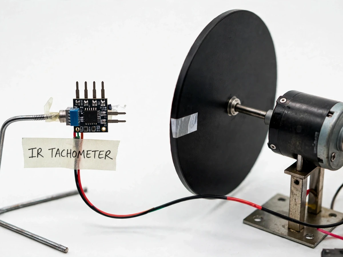
Measuring rotational speed without touching the shaft matters wherever contact would disturb the measurement or wear the sensor — motors, turbines, spindles. The industrial answer is non-contact sensing: a reflective mark on the shaft, an optical sensor watching it, and a counter converting pulses per second into RPM. This project implements exactly that with student hardware: an IR reflective sensor module faces a motor shaft carrying a contrasting mark, each pass generates a pulse, and the Arduino counts pulses over a one-second gate (or measures pulse period) to compute revolutions per minute on a 16x2 LCD. Hold and averaging modes, a low/high range, and a calibration procedure against a known reference make it a complete measurement-instrument build rather than a toy counter.
How it works
- A contrasting (white) mark is fixed on the motor shaft; the IR sensor module is positioned a few millimetres away, facing it.
- Each shaft revolution carries the mark past the sensor once, producing a clean digital pulse via the module's comparator.
- The pulse feeds an Arduino external-interrupt pin, which increments a counter on every rising edge.
- Once per second (the gate time), firmware reads the counter, computes RPM as pulses-per-second × 60 ÷ marks-per-revolution, and resets the counter.
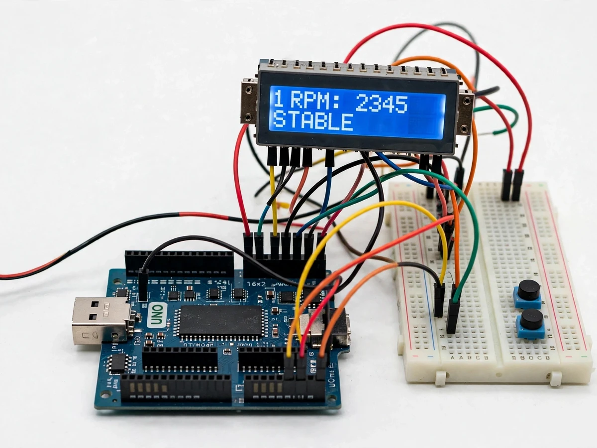
- The result is written to the 16x2 LCD; in average mode the firmware smooths several consecutive gate readings.
- The hold button freezes the displayed value; the range/marks button cycles the marks-per-revolution setting.
Tech stack:
- Arduino Uno (ATmega328P)
- IR reflective sensor module (with comparator)
- 16x2 character LCD
- DC demo motor with marked shaft disc
- Push buttons (hold, mode)
- 5–9 V power supply
- Arduino IDE (C/C++ firmware)
| Parameter | Value |
|---|---|
| Measurement range | Design target approximately 30–9,999 RPM (expected) |
| Sensing | Reflective IR, non-contact, a few mm standoff (design) |
| Gate time | 1 second standard; average mode over 5 gates (design) |
| Display | 16x2 character LCD, RPM with hold/average (design) |
| Marks per rev | 1–4, firmware-selectable (design) |
| Accuracy | Design target approximately ±1% of reading after buyer calibration (expected) |
| Power | 5–9 V supply (design) |
Project features
- [Non-contact IR sensing] A reflective IR sensor detects a contrasting mark on the rotating shaft — nothing touches the shaft, so the measurement adds no load.
- [Interrupt-driven counting] Shaft pulses are captured on a hardware interrupt for accurate counting even at high RPM, independent of LCD update timing.
- [Live RPM on 16x2 LCD] Revolutions per minute update continuously on the character LCD with a stable, readable refresh rate.
- [Hold and average modes] A push button freezes the reading (hold); a second mode averages over multiple gates to smooth fluctuating speeds.
- [Marks-per-revolution setting] Firmware supports 1 or multiple marks per revolution, configurable for different shaft setups.
- [Demo motor included] A DC motor with a marked disc is part of the kit, so the instrument is demonstrated end to end out of the box.
- [Calibration procedure] The report includes a buyer-run procedure to verify readings against a reference (e.g. a second instrument or a known supply frequency).
What is included
- IR sensor head with mounting stand
- Demo DC motor with marked shaft disc
- Arduino Uno with tachometer firmware
- 16x2 LCD and control buttons
- Calibration and operating procedure
- Project report PDF (optical sensing, interrupts, RPM computation, calibration)
- PPT presentation for final review
- Viva Q&A preparation document
Limitations & prerequisites
- Needs a contrasting mark on the shaft and a stable few-mm standoff; dark, tiny or inaccessible shafts need preparation by the user.
- The ±1% figure is a design target verified by the buyer's own calibration — the report documents the procedure rather than claiming a measured result.
- Very low RPM (below ~30) needs a longer gate time for resolution; the firmware documents this tradeoff.
- Ambient IR (direct sunlight on the sensor) can disturb readings; indoor demo lighting is recommended.
- It measures speed only — torque, vibration and direction need separate instruments.
Frequently Asked Questions
How does it measure RPM without touching the shaft?
An IR LED shines on the shaft and a photodiode watches the reflection; a white mark reflects more once per revolution, giving one pulse per turn that the Arduino counts.
Why use an interrupt instead of just checking the pin?
At high RPM pulses arrive microseconds apart; a hardware interrupt catches every edge exactly, while loop polling could miss pulses during LCD updates.
What is the hold button for?
It freezes the current reading on the LCD so you can note it down or photograph it while the motor keeps running.
How do I know the reading is accurate?
The report includes a calibration procedure — compare against a reference instrument or a motor run at a known speed, and adjust the marks-per-revolution setting to match.
Is this project suitable for a final-year project?
Yes — for Electronics, E&TC and Instrumentation programs. It is a complete measurement-instrument build: sensing, interrupt counting, unit conversion and calibration. Suitable for B.E./B.Tech final-year projects in Electronics, E&TC and Instrumentation.
Components & software requirements
- Arduino Uno (ATmega328P)
- IR reflective sensor module (with comparator)
- 16x2 character LCD
- DC demo motor with marked shaft disc
- Push buttons (hold, mode)
- 5–9 V power supply
- Arduino IDE (C/C++ firmware)
Delivery information
Built-to-order project. Delivery timeline is shared after order confirmation based on current queue.
Support terms
Complete documentation, setup guide, and viva preparation included. Support for setup and explanation provided.