
More project photos (3)
The problem
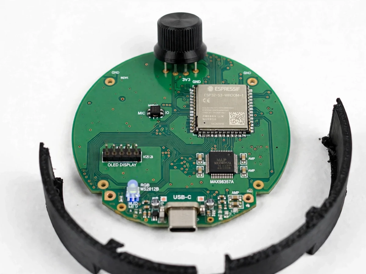
The GPT-6 Astra-inspired AI-designed hardware device is a desk puck that lets a student talk to a coding agent out loud instead of typing, and the project is really about the design method behind it: an LLM drafts the requirements, the component list, the schematic, the firmware skeleton and the 3D-printed enclosure, and the student checks every line of that output against datasheets, design-rule checks and the fabricator's rules. OpenAI reported on 3 November 2026 that its GPT-6 Astra model designed a working device for talking to its Codex coding agent in under a week with no direct human edits, while admitting manufacturing still needed several rounds of review because the model did not consistently respect production limits. This student build copies the workflow, not the claim: the LLM proposes, the student verifies, and a design-audit log records every AI mistake found and fixed, from a wrong footprint to a missing decoupling capacitor.
| This student build | GPT-6 Astra device (reported figures) | Plain voice-assistant speaker | |
|---|---|---|---|
| Design method | LLM drafts, student audits every output, audit log kept | Reported: Astra set requirements, chose parts, laid out the PCB and wrote firmware with no direct human edits | Factory-designed, closed firmware |
| Design time | One semester build, design-audit log included | Reported: working device designed in under a week, prototypes built by a contract manufacturer in under a month | Not applicable |
| Controller | ESP32-S3-WROOM-1 · dual-core up to 240 MHz (Datasheet value) | Not disclosed in the report | Closed, not disclosed |
| Microphone | INMP441 I2S MEMS · 24-bit · 61 dBA SNR (Datasheet value) | Not disclosed in the report | MEMS microphone array, not disclosed |
| Speaker output | MAX98357A · 3.2 W into 4 Ω at 5 V (Datasheet value) | Not disclosed in the report | Small speaker, not disclosed |
| Display | SSD1306 OLED · 128×64 · I2C (Datasheet value) | Not disclosed in the report | None or an LED ring |
| Enclosure | 3D-printed PLA · OpenSCAD model · M3 brass inserts (design target) | Reported: Astra designed the enclosure, a contract manufacturer built the prototypes | Moulded plastic |
| Manufacturing review | Student checks fab design rules before ordering | Reported: several rounds of review and iteration needed | Factory process |
| BenchCAD score | Not applicable — BenchCAD measures AI design models, not student builds | Reported: Astra 0.594 vs a newer unnamed internal model 0.875 | Not applicable |
How it works
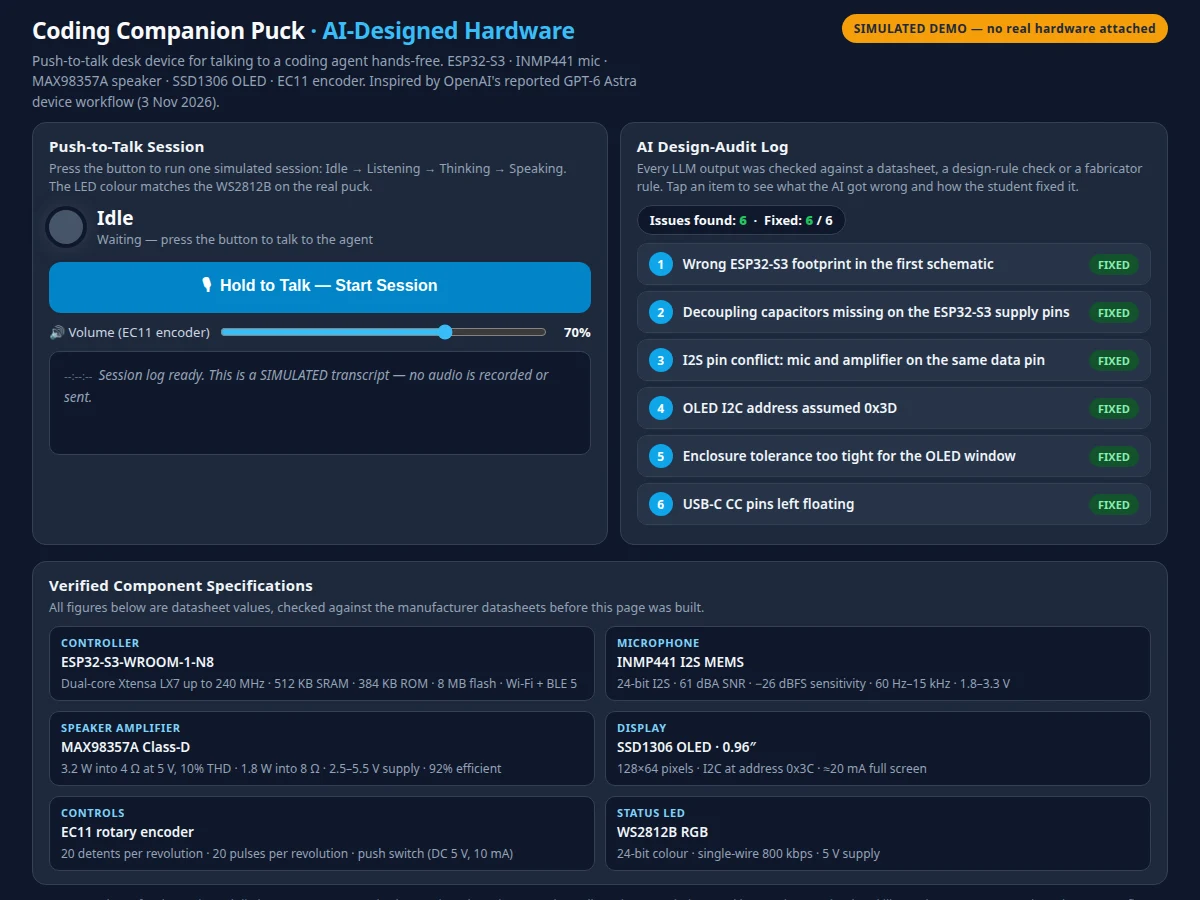
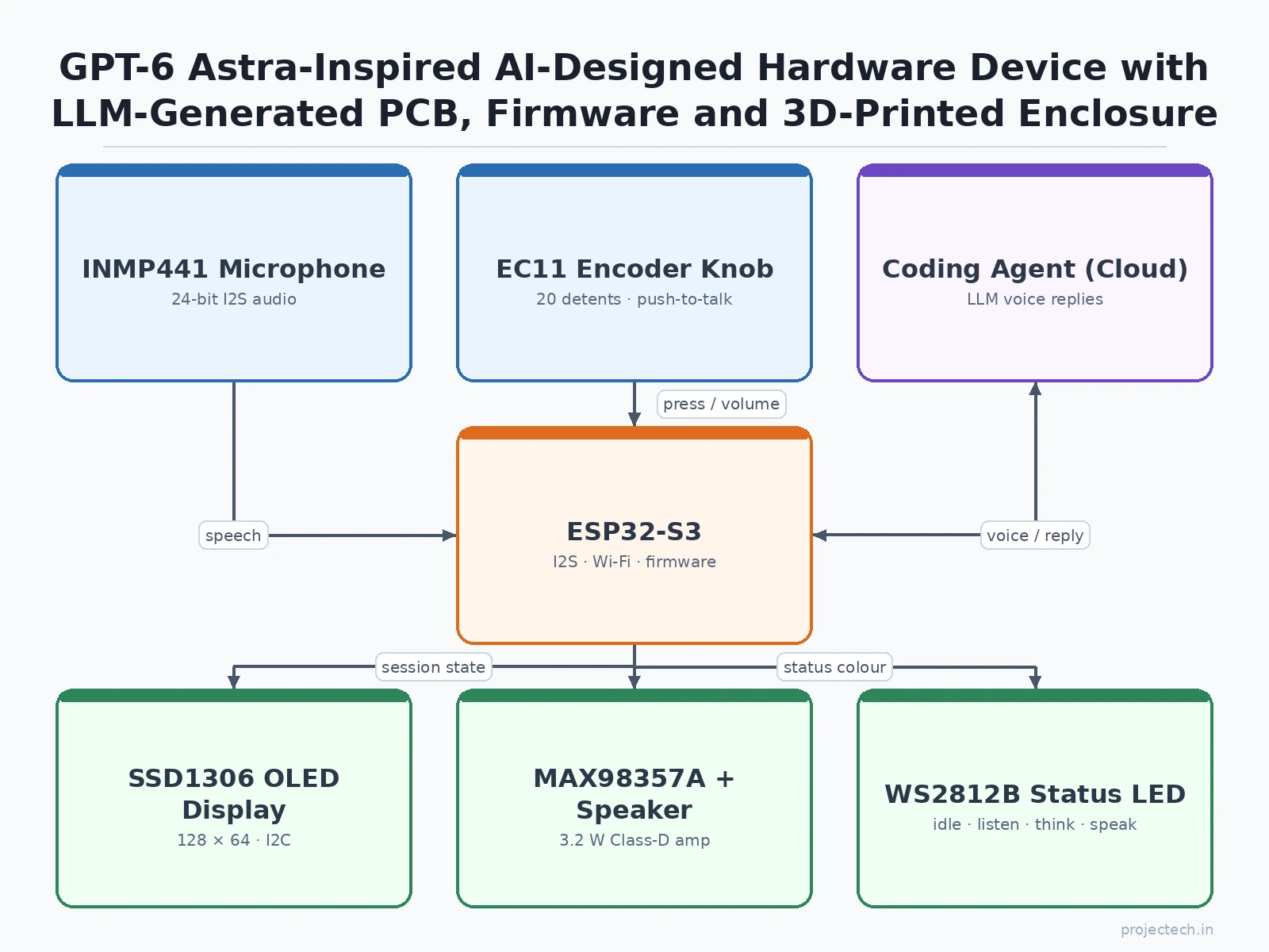
A session starts when the student presses the encoder knob: the WS2812B turns blue, the INMP441 microphone captures speech as 24-bit I2S audio, and the ESP32-S3 streams it over Wi-Fi to the coding agent. The agent's text reply comes back, the puck converts it to speech, and the MAX98357A amplifier plays it through the speaker while the LED turns green and the OLED shows the reply. Behind that loop sits the design workflow that is the real project: the student writes a requirements brief, the LLM drafts the functional specification and component list, the student lays out the two-layer PCB in KiCad from the LLM's placement and routing guidance, runs the design-rule check, and orders the board only after the audit log shows every AI error found and fixed. The enclosure is modelled in OpenSCAD, printed in PLA, and fitted with M3 brass inserts.
- The student writes a requirements brief — what the puck must do, its size, its power source and its interfaces — and the LLM drafts the functional specification and a first component list from it.
- The LLM proposes the component selection — ESP32-S3 module, INMP441 microphone, MAX98357A amplifier, SSD1306 OLED, EC11 encoder and WS2812B LED — and the student checks each part against its datasheet before accepting it.
- The LLM drafts the schematic, and the student redraws it in KiCad, checks every footprint against the part's package drawing, and adds the decoupling capacitors the LLM's first draft omitted.
- The LLM gives placement and routing guidance, and the student lays out the two-layer PCB in KiCad, runs the design-rule check, checks the fabricator's design rules, and logs each AI error found and fixed in the design-audit log.
- The LLM drafts the firmware skeleton and the OpenSCAD enclosure model, and the student reviews the pin assignments — the microphone and the amplifier share one I2S bus, so the firmware must switch the bus direction between capture and playback — and fixes the enclosure tolerances the LLM set too tight.
- The two-layer PCB is fabricated, the parts are soldered, the PLA enclosure is printed and fitted with M3 brass inserts, and the board is mounted inside with the OLED, encoder knob, microphone hole and speaker grille aligned.
- The student runs the test session: press the knob, ask the coding agent a question, hear the reply through the speaker, watch the LED and OLED states change, measure the round-trip latency, and record the measured figures in the report.
Tech stack:
- ESP32-S3-WROOM-1 · dual-core 240 MHz Wi-Fi and BLE module
- INMP441 I2S MEMS microphone · 24-bit digital audio
- MAX98357A I2S Class-D amplifier · 3.2 W into 4 Ω at 5 V
- SSD1306 OLED display · 128×64 pixels · I2C
- EC11 rotary encoder · 20 detents · push switch
- WS2812B RGB status LED · single-wire 800 kbps
- KiCad · 2-layer PCB layout and design-rule checks
- OpenSCAD · 3D-printed PLA enclosure model
| Parameter | Value |
|---|---|
| Build type | Hybrid desk device plus AI-assisted design workflow (design target) |
| Controller | ESP32-S3-WROOM-1-N8 · dual-core Xtensa LX7 up to 240 MHz · 512 KB SRAM · 384 KB ROM · 8 MB flash · Wi-Fi 802.11 b/g/n and Bluetooth 5 LE (Datasheet value) |
| Microphone | INMP441 · 24-bit I2S · 61 dBA SNR · −26 dBFS sensitivity at 1 kHz and 94 dB SPL · 60 Hz to 15 kHz response · 1.8 to 3.3 V supply (Datasheet value) |
| Speaker amplifier | MAX98357A · I2S Class-D · 3.2 W into 4 Ω at 5 V and 10% THD · 1.8 W into 8 Ω at 5 V · 2.5 to 5.5 V supply · 92% efficiency at 8 Ω and 1 W (Datasheet value) |
| Display | SSD1306 OLED · 0.96-inch · 128×64 pixels · I2C at address 0x3C · approximately 20 mA full screen (Datasheet value) |
| Controls | EC11 rotary encoder · 20 detents per revolution · 20 pulses per revolution · push switch rated DC 5 V and 10 mA (vendor specification) |
| Status LED | WS2812B · 24-bit RGB · single-wire 800 kbps data · 5 V supply (Datasheet value) |
| PCB | 2-layer · approximately 80×80 mm · 1.6 mm FR-4 · 1 oz copper (design target) |
| Enclosure | 3D-printed PLA · OpenSCAD model · M3 brass inserts (design target) |
| Power | USB-C · 5 V supply (design target) |
| Round-trip latency | Measured by the student in the test session and recorded in the report — no figure claimed in advance (student-measured) |
| Trend reference | OpenAI research post 3 November 2026 · reported figures only: GPT-6 Astra designed a working device for talking to its Codex coding agent in under a week with no direct human edits · prototypes built by a contract manufacturer in under a month · manufacturing needed several rounds of review and iteration · BenchCAD 2.0 score 0.594 for Astra vs 0.875 for a newer unnamed internal model · never claimed for this build |
| Builder note | The INMP441 microphone and the MAX98357A amplifier share one I2S bus, so the firmware must switch the bus direction between capture and playback — the audit log's pin-conflict entry exists because the LLM's first draft assigned both devices the same data pin. The LLM's first schematic also omitted decoupling capacitors on the ESP32-S3 supply pins; the audit caught it because a decoupling capacitor belongs close to each power pin, and the log records the fix. The 2-layer board keeps routing simple, so the I2S clock and data lines are kept short and away from the switching amplifier output, which the audit log records as a layout rule rather than a measured result. |
Project features
The puck earns its place on a review table because it makes the AI-assisted design workflow visible and testable. Push-to-talk voice is the first capability: press the encoder knob, speak a coding question, and the agent's reply plays back through the speaker while the OLED shows the session state. The design-audit log is the second: every AI output is checked against a datasheet, a design-rule check or a fabricator rule, and each error the LLM made — a wrong footprint, a missing decoupling capacitor, an I2S pin clash — is recorded with its fix. The third is the full hardware loop: an INMP441 microphone captures speech, the ESP32-S3 streams it to the coding agent, and a MAX98357A amplifier drives the reply out of a small speaker. A WS2812B status LED shows idle, listening, thinking and speaking at a glance.
- [Push-to-talk voice sessions] Pressing the EC11 encoder knob starts a session: the WS2812B turns blue, the INMP441 captures speech, the ESP32-S3 streams it to the coding agent, and the reply plays back through the speaker while the OLED shows the session state — implemented in the base build.
- [AI design-audit log] Every LLM output is checked against a datasheet, a design-rule check or a fabricator rule, and each AI error found — a wrong footprint, a missing decoupling capacitor, an I2S pin clash, an enclosure tolerance too tight — is logged with its fix — implemented in the base build.
- [I2S microphone capture] The INMP441 MEMS microphone captures speech as 24-bit I2S audio with 61 dBA SNR and −26 dBFS sensitivity at 1 kHz and 94 dB SPL (Datasheet value), with a flat response from 60 Hz to 15 kHz — implemented in the base build.
- [I2S speaker playback] The MAX98357A Class-D amplifier drives the agent's spoken reply at 3.2 W into a 4 Ω speaker at 5 V and 10% THD (Datasheet value), with five selectable gains from 3 dB to 15 dB — implemented in the base build.
- [OLED session display] The SSD1306 0.96-inch OLED shows the session state, the volume and short status lines at 128×64 pixels over I2C at address 0x3C (Datasheet value), so the puck's state is readable without a laptop — implemented in the base build.
- [Rotary encoder control] The EC11 encoder gives 20 detents per revolution for volume control, and its push switch starts and ends a voice session, so the whole device is operated from one knob — implemented in the base build.
- [WS2812B status LED] One addressable RGB LED shows the session state in colour — idle, listening, thinking and speaking — driven over a single wire at 800 kbps with 24-bit colour (Datasheet value) — implemented in the base build.
- [Offline local-model mode] Future scope only, not implemented: the puck talks to a small model running on the student's own machine instead of a cloud coding agent, listed as an extension rather than a claimed feature, since the base build needs a network connection to its agent.
What is included
- Custom 2-layer PCB with ESP32-S3 module, INMP441 microphone, MAX98357A amplifier, OLED header, EC11 encoder, WS2812B LED and USB-C power, assembled and tested
- 3D-printed PLA enclosure with M3 brass inserts, with the OLED window, encoder knob, microphone hole and speaker grille aligned to the board
- Push-to-talk firmware: session state machine, I2S capture and playback, OLED status display, encoder volume control
- Design-audit log: every AI error found and fixed, with the datasheet, design-rule check or fabricator rule that caught it
- KiCad schematic and PCB files and the OpenSCAD enclosure model
- Setup and test guide (agent connection, first-session checklist, round-trip latency measurement procedure)
- Project report PDF (Astra background with reported figures labelled as reported, the AI-assisted workflow, the audit log, the student's own measured test results)
- PPT presentation for final review
- Viva Q&A preparation document (why the LLM drafts and the student verifies, how I2S audio works, why Astra still needed manufacturing review, what the audit log proves)
Limitations & prerequisites
- Not the device OpenAI built: this is a student puck inspired by the reported Astra workflow; it shares no parts, performance or capability with OpenAI's device and must never be presented as one.
- LLM outputs can be wrong: the model can suggest a wrong footprint, omit decoupling capacitors, clash I2S pins or set an enclosure tolerance too tight — every AI output must pass the human audit before fabrication, and the audit log is the proof that it did.
- Needs a coding-agent connection: the puck talks to an external coding agent over Wi-Fi, so it needs network access and valid agent credentials; without them it is a microphone and a speaker with no one to talk to.
- Audio limits: a single MEMS microphone and a small 3.2 W speaker suit a quiet desk, not a noisy room or a hall, and the microphone hears the room as well as the speaker.
- 2-layer routing limits: the approximately 80×80 mm two-layer board keeps routing simple, so high-speed signals and dense parts need care and the audit log records the compromises made.
- Latency is measured, not promised: round-trip time depends on the network and the agent, so the report records the student's own measured figures instead of claiming a number in advance.
- PLA enclosure: 3D-printed PLA is a prototype material, not a moulded product housing, so it suits a desk prototype and a review table, not daily carrying.
Frequently Asked Questions
Is this project suitable for a final-year project?
Yes, for Electronics, IoT and AI and Machine Learning programmes, because it combines embedded hardware, I2S audio, PCB design, firmware and an AI-assisted design workflow into one testable build, with a clear review thread around the design-audit log and the human verification of every AI output. The design-audit log documents the workflow, the hardware and the test results, so the project reads as engineering work rather than a prompt-and-pray demo.
Is this the device OpenAI built?
No. OpenAI reported on 3 November 2026 that its GPT-6 Astra model designed a working device for talking to its Codex coding agent in under a week with no direct human edits, that a contract manufacturer built prototypes in under a month, and that Astra scored 0.594 on BenchCAD 2.0 against 0.875 for a newer unnamed internal model. This is a student puck that copies the workflow — LLM drafts, human audits — not the device, and it shares no parts with OpenAI's build.
What does the AI design, and what does the student do?
The LLM drafts the requirements, the component list, the schematic, the placement and routing guidance, the firmware skeleton and the enclosure model, and the student checks every output against datasheets, design-rule checks and fabricator rules. The student lays out the PCB in KiCad, fixes the footprint, decoupling and pin errors the audit finds, and keeps the design-audit log that records each one.
How does a push-to-talk session work?
Pressing the encoder knob starts a session: the WS2812B turns blue, the INMP441 captures speech as 24-bit I2S audio, and the ESP32-S3 streams it over Wi-Fi to the coding agent. The agent's text reply comes back, the puck converts it to speech, and the MAX98357A plays it through the speaker while the LED turns green and the OLED shows the reply.
What will I receive with the project?
The assembled puck PCB in its 3D-printed enclosure, the push-to-talk firmware, the design-audit log, the KiCad schematic and PCB files, the OpenSCAD enclosure model, the setup and test guide, the project report, the presentation and the viva Q&A document. A laptop, a USB-C supply and a coding-agent connection are needed, all covered in the setup guide.
What are the main limitations?
The LLM can make design errors, so the human audit is mandatory and every AI output is checked before fabrication. The puck needs a network connection and valid agent credentials, the single microphone and small speaker suit a quiet desk, the two-layer board limits dense routing, and the round-trip latency is measured by the student rather than promised in advance.
Components & software requirements
- ESP32-S3-WROOM-1 · dual-core 240 MHz Wi-Fi and BLE module
- INMP441 I2S MEMS microphone · 24-bit digital audio
- MAX98357A I2S Class-D amplifier · 3.2 W into 4 Ω at 5 V
- SSD1306 OLED display · 128×64 pixels · I2C
- EC11 rotary encoder · 20 detents · push switch
- WS2812B RGB status LED · single-wire 800 kbps
- KiCad · 2-layer PCB layout and design-rule checks
- OpenSCAD · 3D-printed PLA enclosure model
Delivery information
Built-to-order project. Delivery timeline is shared after order confirmation based on current queue.
Support terms
Complete documentation, setup guide, and viva preparation included. Support for setup and explanation provided.
Download free synopsis (PDF)
Enter your name and WhatsApp number — the synopsis PDF downloads immediately. We may send occasional project updates on WhatsApp; no spam.