
More project photos (2)
The problem
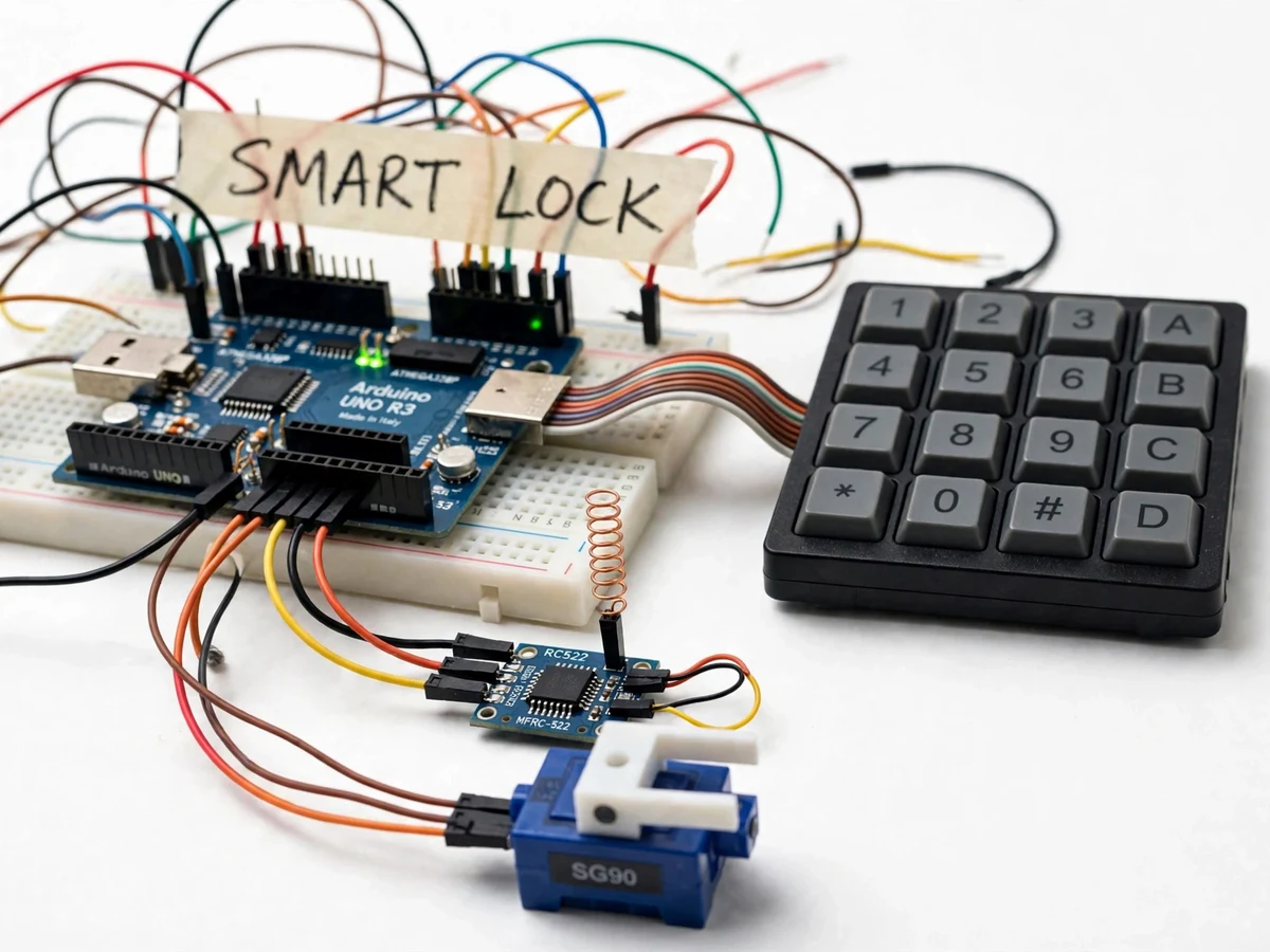
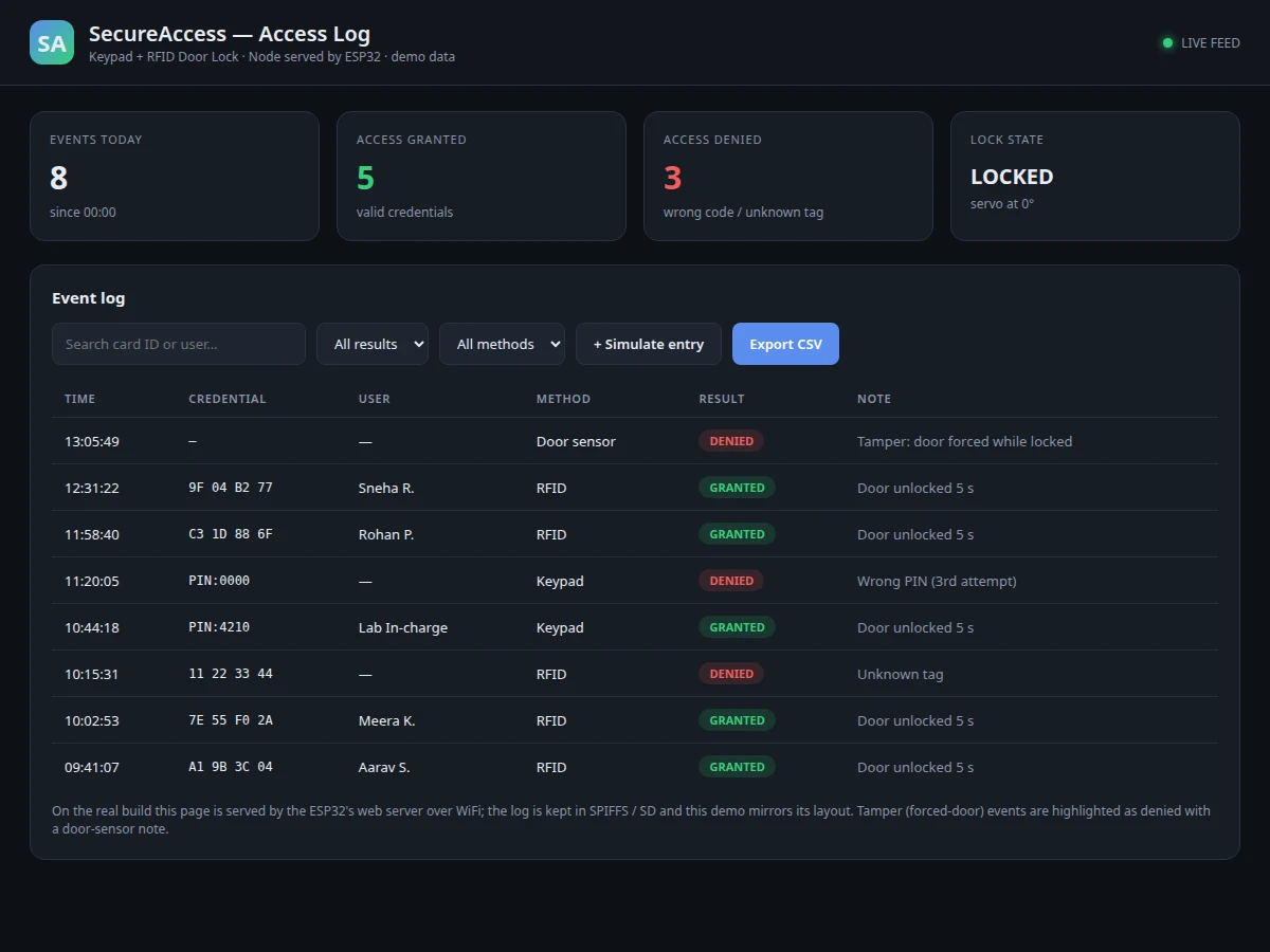
A lock that only one key opens is a single point of failure; a lock with no record of who entered is a security blind spot. Real access systems solve both with credentials plus audit — PINs for people, cards for convenience, and a log that answers "who came in, and when?" This project builds that system at student scale: an ESP32 reads a 4x4 matrix keypad and an RC522 RFID reader, drives a servo as the door latch, and serves a live access-log dashboard over WiFi. Enter the right PIN or tap an enrolled card and the latch opens with a green confirmation; get it wrong three times and the unit locks out with a buzzer, logging the attempt as denied. The demo walks the examiner through granting access both ways, triggering the lockout, then opening the dashboard to show every event timestamped, filterable and exportable to CSV. It is the rare hardware project with a genuinely useful software face — and the dashboard is a real working demo, screenshotted for the gallery.
How it works
- The ESP32 continuously scans the 4x4 keypad matrix and polls the RC522 reader for cards in its field.
- A completed PIN entry or a card tap is checked against the enrolled credential store in flash memory.
- On a match, the firmware drives the servo to the open position, shows green confirmation, and logs a granted event with timestamp and credential type.
- On a mismatch, a denied event is logged, the buzzer sounds, and the failure counter increments toward lockout.
- Three consecutive failures engage a timed lockout during which all inputs are ignored and logged.
- Every event is pushed to the web dashboard's table over WiFi, where it can be searched, filtered by status, and exported to CSV.
Tech stack:
- ESP32 DevKit (WiFi + web server)
- 4x4 matrix membrane keypad
- RC522 RFID reader (13.56 MHz, SPI)
- SG90 servo (latch actuator)
- Buzzer + status LEDs
- Embedded web dashboard (HTML/CSS/JS served from firmware)
- Arduino IDE (C/C++ firmware)
- 5 V regulated supply
| Parameter | Value |
|---|---|
| Controller | ESP32 DevKit, 240 MHz dual-core |
| Credentials | 4–6 digit PIN via keypad; MIFARE UID cards via RC522 (3–5 cm read distance) |
| Actuator | SG90 servo latch, configurable hold-open time (default ~5 s) |
| Lockout | 3 failed attempts → timed lockout (configurable, default 60 s) with buzzer |
| Dashboard | Live event table: timestamp, credential, granted/denied; search, filter, CSV export |
| Logging | Events stored in flash ring buffer + served live; design target 500 events |
| Network | ESP32 web server on local WiFi (station or AP mode) |
| Power | 5 V USB; servo on separate rail recommended |
Project features
- [Dual credential entry] The door opens for either a 4–6 digit keypad PIN or an enrolled RFID card/tag — two independent paths, one latch.
- [Servo latch actuation] An SG90 servo drives the bolt mechanism with configurable open-hold time before auto-relocking, demonstrating real actuator control.
- [Web access-log dashboard] The ESP32 serves a live dashboard: event table with timestamps, credential type, granted/denied status, plus search, filtering and CSV export.
- [Wrong-attempt lockout] Three consecutive failures trigger a timed lockout with buzzer alert; every denied attempt is logged with its timestamp.
- [Card and PIN enrollment] New RFID cards and PIN codes are enrolled through an admin procedure on the device — no PC tooling needed.
- [Tamper and door sensing] A door-position input logs forced-entry style events (door opened without credential), showing how real systems detect bypass.
- [Live event simulation] The dashboard demo can simulate access events for presentation, so the log behaviour is demonstrable without wearing out the keypad.
What is included
- Working door-lock prototype (ESP32, keypad, RC522, servo latch, buzzer, card set)
- Complete firmware source code (credential handling, servo control, lockout logic, web server)
- Working web dashboard demo (single-file HTML, same code family as the shipped firmware UI)
- Enrollment and admin procedure guide
- Circuit and wiring documentation
- Project report PDF (access-control background, dual-credential design, embedded web architecture)
- PPT presentation for final review
- Viva Q&A preparation document (keypad scanning, RFID, servo PWM, HTTP in firmware)
- Setup and demonstration guide
Limitations & prerequisites
- The servo latch demonstrates the locking mechanism; fitting it to a real door (strike plate, mechanical strength) is buyer-done and outside an electronics kit's scope.
- RFID identification is UID-based (MIFARE Classic), suitable for a demo access system, not a high-security installation — the report states this plainly.
- The web dashboard is served on the local network; there is no cloud backup of the log in this build.
- The event buffer is a flash ring with a design target of ~500 events; older events roll off as new ones arrive.
- Like all student prototypes, this is not a certified security product; it demonstrates access-control principles.
Frequently Asked Questions
How do you open the lock?
Enter the enrolled 4–6 digit PIN on the 4x4 membrane keypad, or tap an enrolled RFID card or keyfob on the RC522 reader — either credential drives the SG90 servo latch to the open position for a configurable hold time before it auto-relocks. A green LED and a dashboard event confirm every granted access, so the mechanism's behaviour is visible as well as audible.
What does the web dashboard show?
A live table of every access event served by the ESP32 itself: timestamp, credential type (PIN or card), the card UID or PIN slot, and granted/denied status. The table supports text search and status filtering, and the whole log exports to CSV with one click. The demo build can also simulate events, so the dashboard's behaviour is presentable without wearing out the keypad.
What happens on wrong PIN attempts?
Each failed attempt is logged as denied with its timestamp, the buzzer sounds, and a failure counter increments. Three consecutive failures engage a timed lockout — 60 seconds by default, configurable — during which all keypad and card inputs are ignored and logged. The lockout is the behaviour that separates a toy from an access-control demonstration.
How are new users enrolled?
An admin procedure on the device handles enrollment: an admin credential opens enroll mode, then new RFID cards are tapped and new PINs typed in, each stored against a user slot in the ESP32's flash. No PC software is involved. The procedure card walks through adding, listing and deleting credentials, which is also the part of the demo that shows administrative control.
What are the main limitations?
The servo demonstrates the latch; fitting real door hardware is buyer-done. RFID is UID-based (MIFARE Classic), fine for a demonstration access system but not high-security — the report says so directly. The dashboard is local-network only with no cloud backup, and the event store is a flash ring buffer targeting about 500 events before older entries roll off.
Is this project suitable for a final-year project?
Yes — for Electronics, Computer and IoT programs. Dual-credential state logic, servo actuation, wrong-attempt lockout design and a genuinely working embedded web dashboard give it unusual depth for a hardware build. The dashboard screenshot in the gallery is from the real demo, and the log-export behaviour is easy to examine live. Suitable for B.E./B.Tech final-year projects in Electronics, Computer and IoT engineering.
Components & software requirements
- ESP32 DevKit (WiFi + web server)
- 4x4 matrix membrane keypad
- RC522 RFID reader (13.56 MHz, SPI)
- SG90 servo (latch actuator)
- Buzzer + status LEDs
- Embedded web dashboard (HTML/CSS/JS served from firmware)
- Arduino IDE (C/C++ firmware)
- 5 V regulated supply
Delivery information
Built-to-order project. Delivery timeline is shared after order confirmation based on current queue.
Support terms
Complete documentation, setup guide, and viva preparation included. Support for setup and explanation provided.