
More project photos (3)
The problem
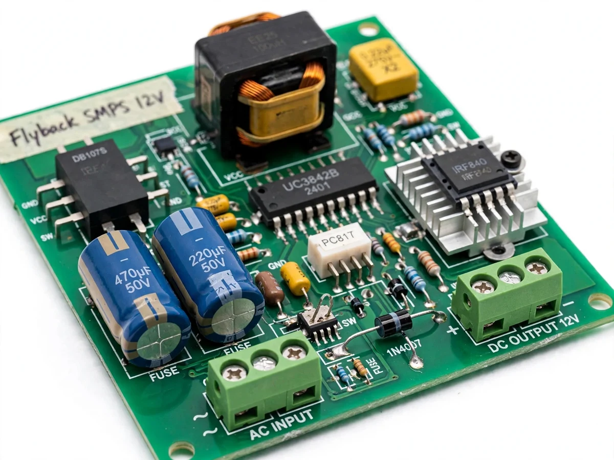
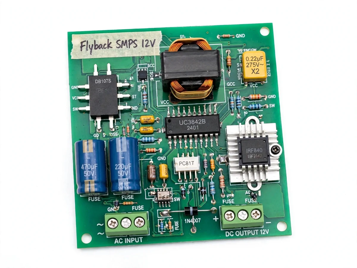
Every electronic device needs clean DC from the mains, and the heavy, wasteful linear supply has long given way to the switch-mode supply — yet most students never build one, because mains voltage plus custom magnetics feels intimidating. The flyback converter is the classic low-power isolated topology behind phone chargers and standby supplies: a single switch, a transformer that doubles as the energy-storage inductor, and inherent primary-to-secondary isolation. This project makes a flyback buildable as student work: a UC3842 current-mode PWM controller (simple, thoroughly documented), a hand-wound EE-core transformer built to an included winding specification, optocoupler-plus-TL431 feedback for regulation, and an input stage with EMI filter, fuse and NTC inrush limiter. Students calculate the transformer turns ratio, wind the transformer, assemble the board, then verify line and load regulation and output ripple with an oscilloscope — a complete design-to-test power-electronics exercise rather than a kit assembly.
Universal input 85 to 265 V AC through fuse, NTC inrush limiter and EMI filter.
How it works
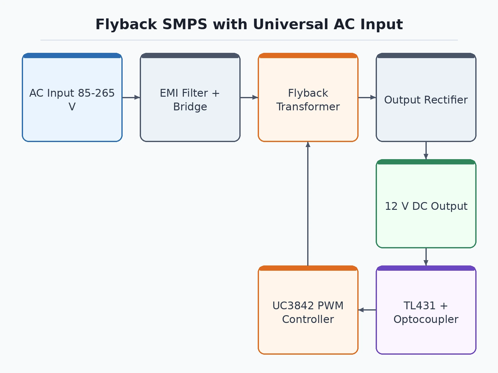
- Mains (85–265 V AC) passes the fuse, NTC inrush limiter and EMI filter; a bridge rectifier plus bulk capacitor produces roughly 120–375 V DC.
- The UC3842 oscillator (Rt/Ct set for about 65 kHz) drives a power MOSFET switching the transformer primary.
- During the on-time, energy stores in the gapped transformer core; during the off-time it transfers to the secondary — the flyback action.
- The secondary diode and LC filter produce 12 V DC, while an auxiliary winding powers the UC3842 after start-up.
- A TL431 plus PC817 feedback loop compares the output against the reference and trims the UC3842 duty cycle for line and load regulation.
- An RCD snubber clamps the MOSFET drain spike caused by leakage inductance every switching cycle.
- Protection layers: cycle-by-cycle current limit, output short-circuit foldback and the controller's undervoltage lockout.
Tech stack:
- UC3842 current-mode PWM controller
- Custom-wound EE25-class ferrite flyback transformer
- 600 V-class power MOSFET with RCD snubber
- PC817 optocoupler + TL431 shunt regulator for isolated feedback
- Bridge rectifier, bulk electrolytic capacitor, NTC thermistor, mains fuse
- Common-mode choke with X/Y capacitors for the EMI filter
- Double-sided PCB with marked oscilloscope test points
| Parameter | Value |
|---|---|
| Topology | Flyback converter, transformer-isolated |
| Controller | UC3842 current-mode PWM IC |
| Input | 85–265 V AC, 50/60 Hz |
| Output | 12 V DC, up to 2 A (24 W design target) |
| Switching frequency | ~65 kHz set by Rt/Ct (design target) |
| Line/load regulation | ±5% design target (TL431 + optocoupler loop) |
| Output ripple | <120 mVpp design target at full load |
| Efficiency | ~80% design target at full load |
| Isolation | Transformer-isolated; primary–secondary creepage observed in PCB layout |
| Protections | Mains fuse, NTC inrush limiter, cycle-by-cycle current limit, short-circuit foldback, UVLO |
Project features
- Universal AC Input: 85–265 V AC at 50/60 Hz through a bridge rectifier and bulk capacitor, so the supply works on Indian and international mains.
- UC3842 Current-Mode Control: an industry-standard current-mode PWM controller IC; cycle-by-cycle current limiting is built into the control law.
- Custom-Wound Flyback Transformer: an EE25-class ferrite core wound to the included turns specification (primary, secondary, auxiliary) that also forms the isolation barrier.
- Optocoupler plus TL431 Feedback: a secondary-side TL431 reference drives a PC817 optocoupler for isolated voltage feedback and tight line/load regulation.
- Short-Circuit Protection: current-mode control with secondary current limiting; the supply recovers automatically when the fault is cleared.
- Input EMI Filter: a common-mode choke with X and Y capacitors keeps switching noise off the mains input.
- Soft Start and UVLO: the UC3842's undervoltage lockout and soft-start ramp prevent transformer saturation during power-up.
- Marked Test Points: clearly labeled test points for the switching waveform, output ripple and feedback-loop probing with an oscilloscope.
What is included
- Assembled and load-tested SMPS board in enclosure-ready form
- Transformer winding specification (core, turns, wire gauge, air gap)
- Schematic, PCB layout with Gerbers, and full bill of materials
- Design calculation sheet (turns ratio, snubber, feedback-loop values)
- Test procedure: line/load regulation, ripple measurement and thermal check
- Project report PDF, PPT presentation and viva Q&A document
Advantages
- Universal 85 to 265 V AC input at 50/60 Hz through a bridge rectifier and bulk capacitor means the same supply works on Indian and international mains.
- The industry-standard UC3842 current-mode PWM controller gives cycle-by-cycle current limiting as part of its control law, with short-circuit protection that recovers automatically when the fault is cleared.
- The custom-wound EE25-class ferrite transformer, wound to the included turns specification for primary, secondary and auxiliary, also forms the isolation barrier of the 24 W, 12 V DC design.
- Secondary-side TL431 reference driving a PC817 optocoupler gives isolated voltage feedback for tight line and load regulation across line and load changes.
- A common-mode choke with X and Y capacitors keeps switching noise off the mains input, and clearly labeled test points let students probe the switching waveform, output ripple and feedback loop with an oscilloscope.
- The UC3842's undervoltage lockout and soft-start ramp prevent transformer saturation during power-up.
Disadvantages
- This project works directly with lethal mains voltage: assembly, first power-up and testing must be done under qualified supervision with an isolation transformer and proper earthing, and it is not suitable for unsupervised beginners.
- Output specifications such as regulation, ripple and efficiency are design targets verified by the documented test procedure during the build; the report presents the build's measured numbers, never pre-claimed ones.
- The prototype is not a certified product - no BIS, UL or CE certification - so it is an educational build, not for commercial sale or permanent installation.
- The transformer is hand-wound to the specification sheet, and winding quality affects leakage inductance and efficiency, so the procedure includes a winding quality check.
- Hold-up time and transient response are design-dependent and measured, not guaranteed figures, and heatsinking is sized for the 24 W design target, so sustained overload shortens component life.
Limitations & prerequisites
- SAFETY FIRST: this project works directly with lethal mains voltage. Assembly, first power-up and testing must be done under qualified supervision with an isolation transformer and proper earthing — it is not suitable for unsupervised beginners.
- Output specifications (regulation, ripple, efficiency) are design targets verified by the documented test procedure during your build; the report presents your build's measured numbers, never pre-claimed ones.
- The prototype is not a certified product — no BIS/UL/CE certification. It is an educational build, not for commercial sale or permanent installation.
- The transformer is hand-wound to the specification sheet; winding quality affects leakage inductance and efficiency, so the procedure includes a winding quality check.
- Hold-up time and transient response are design-dependent; the test procedure measures them but they are not guaranteed figures.
- Heatsinking is sized for the 24 W design target; sustained overload shortens component life — the protection foldback is a safety net, not a rating.
Frequently Asked Questions
Is this project suitable for a final-year project?
Yes — for Electrical and Electronics programs. It covers magnetics design, current-mode control, isolated feedback loops and EMI filtering, with viva material on flyback versus forward topology, what the RCD snubber does, and how the TL431 loop sets the output voltage.
Is it safe to build?
Only under supervision: the safety guide mandates an isolation transformer for bench testing, proper earthing, a mains fuse and qualified oversight for first power-up.
Which controller IC is used?
The UC3842 current-mode PWM controller; the design sheet explains its oscillator, current-sense input and undervoltage lockout.
Can the output voltage or power be changed?
The transformer turns specification and feedback divider set the output — 5 V and 24 V variants are documented customizations, each needing its own winding specification.
What will I receive with the project?
The assembled and tested board, transformer winding specification, schematic and Gerbers, BOM, design calculations, test procedure, report, PPT and viva Q&A. Suitable for B.E./B.Tech final-year projects in Electrical and Electronics Engineering.
Components & software requirements
- UC3842 current-mode PWM controller
- Custom-wound EE25-class ferrite flyback transformer
- 600 V-class power MOSFET with RCD snubber
- PC817 optocoupler + TL431 shunt regulator for isolated feedback
- Bridge rectifier, bulk electrolytic capacitor, NTC thermistor, mains fuse
- Common-mode choke with X/Y capacitors for the EMI filter
- Double-sided PCB with marked oscilloscope test points
Delivery information
Built-to-order project. Delivery timeline is shared after order confirmation based on current queue.
Support terms
Complete documentation, setup guide, and viva preparation included. Support for setup and explanation provided.
Download free synopsis (PDF)
Enter your name and WhatsApp number — the synopsis PDF downloads immediately. We may send occasional project updates on WhatsApp; no spam.