
More project photos (2)
The problem
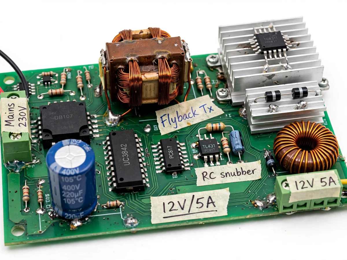
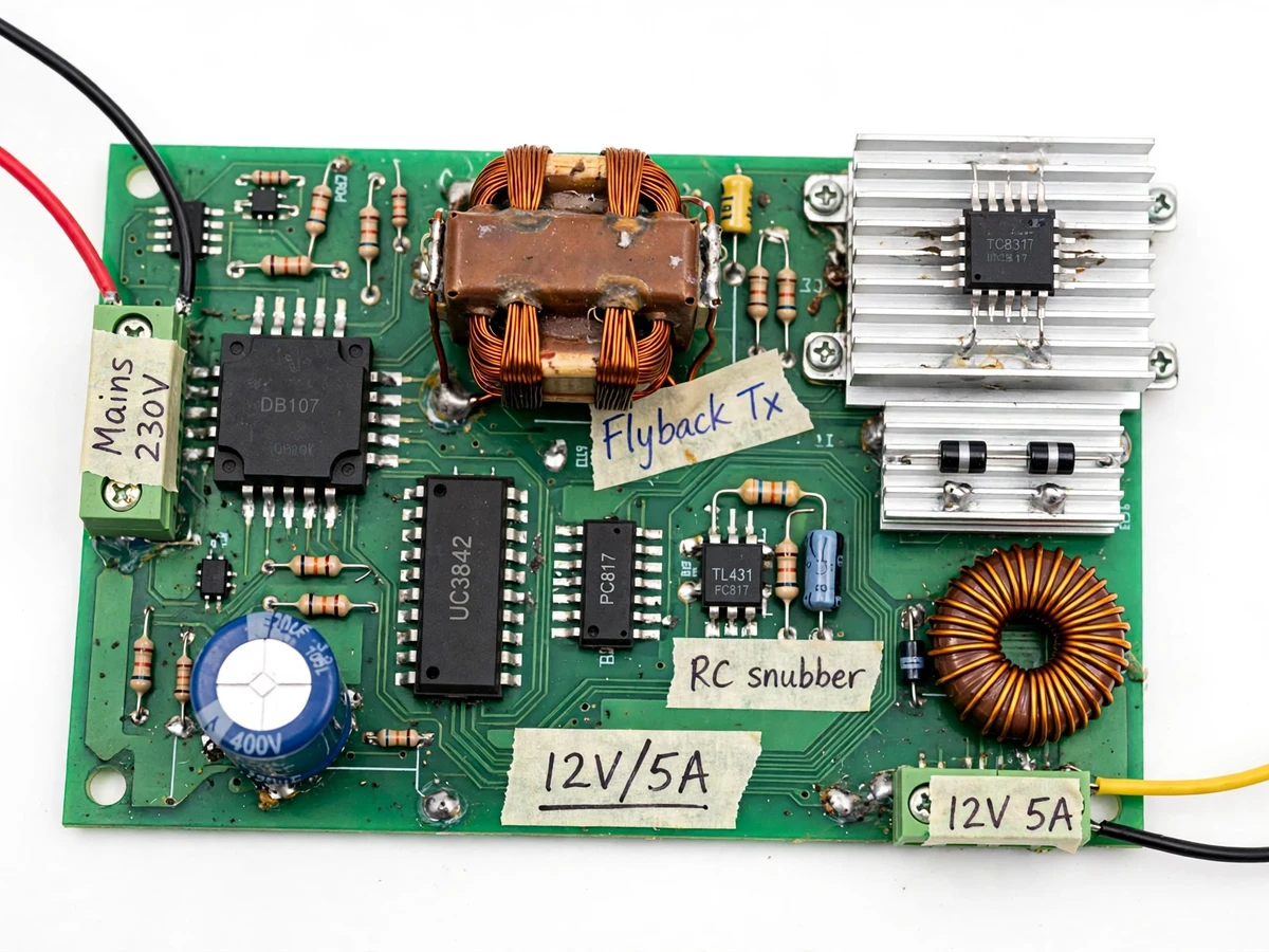
The DIY 12V 5A SMPS is a 60 W flyback-mode switched-mode power supply that converts 230 V AC mains into a regulated 12 V DC output at up to 5 A. Most student power-supply projects stop at the linear 7805 regulator — bulky, hot and inefficient — while real equipment runs on switch-mode supplies that switch at tens of kilohertz through a magnetic core. Commercial SMPS boards are sealed, potted and explained only through datasheet block diagrams, so students never see the real design decisions. Building one from scratch forces the student through every one of them — selecting a PWM controller, designing a current-mode feedback loop, hand-winding a gapped EE-core flyback transformer, clamping the MOSFET drain spike with an RC snubber, and keeping the lethal primary side safely isolated from the low-voltage secondary. The result is a working 60 W supply that can run LED strips, motors or charge batteries.
Input fuse, MOV surge guard and EMI filter protect the mains inlet.
Follow the working sequence
How it works
The SMPS conversion chain starts at the 230 V AC mains inlet: an input fuse, MOV surge suppressor and common-mode EMI filter feed a bridge rectifier that charges a 400 V bulk capacitor to roughly 325 V DC (peak of 230 V AC, a design value). The UC3842 PWM controller then chops this high-voltage DC through the primary winding of the hand-wound flyback transformer at approximately 65 kHz, driving a power MOSFET under current-mode control. During each on-time, energy is stored in the gapped ferrite core; during the off-time it is released into the secondary winding, where fast-recovery diodes rectify it and an LC filter smooths it into clean 12 V DC. A TL431 + PC817 optocoupler samples the output and closes an isolated feedback loop back to the UC3842, adjusting the duty cycle to hold 12 V from no-load to 5 A, while cycle-by-cycle current sensing shuts the MOSFET off instantly on overload.
- The 230 V AC mains passes through the input fuse, MOV and EMI filter into the bridge rectifier, which charges the 400 V bulk electrolytic capacitor to roughly 325 V DC (rectified peak, design value).
- The UC3842 starts its oscillator (Rt/Ct set for approximately 65 kHz, design target) once its supply crosses the 16 V UVLO turn-on threshold (datasheet); soft start ramps the duty cycle gradually.
- The UC3842 drives the MOSFET gate, switching the primary of the gapped EE-core flyback transformer; during on-time, energy stores in the core's air gap while the secondary diode blocks.
- On switch-off, the stored energy transfers to the secondary winding; fast-recovery output diodes rectify it and the LC filter smooths ripple toward the <120 mVpp design target.
- The TL431 senses the 12 V output against its 2.5 V internal reference (datasheet) and drives the PC817 optocoupler LED; the phototransistor feeds the UC3842 error amplifier across the isolation boundary.
- The controller trims the duty cycle each cycle to hold 12 V DC from light load to full 5 A, with cycle-by-cycle current limiting shutting the MOSFET off on any over-current event.
- The RC snubber across the primary clamps the MOSFET drain spike at turn-off — the builder's note: this snubber is the single most common fix for flyback MOSFET failures in student builds.
Tech stack:
- UC3842 current-mode PWM controller
- EE ferrite-core flyback transformer (hand-wound, gapped)
- PC817 optocoupler · TL431 shunt regulator
- Power MOSFET · aluminium heatsinks
- DB107 bridge rectifier · 400 V bulk capacitor
- RC snubber · output LC filter
- Input fuse · MOV · EMI filter
- Hand-wound magnetics design calculations
| Parameter | Value |
|---|---|
| Input | 230 V AC ±10%, 50 Hz (design target) |
| Output | 12 V DC, 5 A, 60 W (design target) |
| Controller | UC3842 current-mode PWM (datasheet) |
| UVLO thresholds | 16 V turn-on / 10 V turn-off (datasheet) |
| Switching frequency | Approximately 65 kHz (design target, set by Rt/Ct) |
| Efficiency | Approximately 80–85% (design target, not measured) |
| Output ripple | <120 mVpp (design target) |
| Feedback reference | TL431 internal 2.5 V (datasheet) |
| Isolation | PC817 optocoupler across mains boundary (as designed) |
| Protection | Input fuse + MOV + EMI filter + cycle-by-cycle current limit (as built) |
| Core | EE ferrite core with air gap (hand-wound) |
Project features
The heart of this SMPS is the UC3842, the classic Unitrode current-mode PWM controller — an 8-pin DIP IC whose oscillator frequency is set by a single Rt/Ct pair (approximately 65 kHz here, a design target) and whose cycle-by-cycle current limit turns an ordinary flyback stage into a protected one. Second is the magnetic design: the flyback "transformer" is really a coupled inductor, so the EE ferrite core is assembled with a deliberate air gap — energy is stored in the gap during the MOSFET on-time and released to the secondary during the off-time, the single most important design idea in the project. Third is the isolated regulation loop: a TL431 shunt regulator on the secondary drives a PC817 optocoupler across the mains isolation boundary, so the output holds at 12 V with no galvanic connection back to the primary.
- [UC3842 current-mode PWM control] The 8-pin DIP controller sets switching frequency with Rt/Ct (approximately 65 kHz, design target), gives cycle-by-cycle current limiting, soft start and UVLO (16 V on / 10 V off, datasheet) — no microcontroller or firmware involved.
- [Hand-wound gapped EE-core flyback transformer] The flyback "transformer" is really a coupled inductor: energy stores in the core's air gap during MOSFET on-time and releases to the secondary during off-time — which is why the core needs the gap. Full winding sheet (turns, wire gauges, gap method) is included.
- [Optocoupler + TL431 isolated feedback] A TL431 shunt regulator senses the 12 V output against its 2.5 V internal reference (datasheet) and drives a PC817 optocoupler across the mains isolation boundary, holding the output from no-load to full 5 A.
- [Over-current shutdown] Cycle-by-cycle current sensing on the MOSFET source shuts the switch off within the same switching period on overload or short circuit, protecting both the MOSFET and the load.
- [Soft start] The UC3842's internal soft start ramps the duty cycle on power-up, limiting inrush stress on the MOSFET and the bulk capacitor.
- [Input fuse + MOV + EMI filter] The mains inlet is protected by a glass fuse, a metal-oxide varistor against surges, and a common-mode EMI filter — the parts of a real supply students usually never see.
- [Output LC filtering] Fast-recovery output diodes plus an inductor-capacitor filter smooth the switching waveform toward the <120 mVpp ripple design target.
- [LED status indicator] A green LED on the 12 V rail gives instant visual confirmation that the loop is regulating; it doubles as the minimum-load bleeder.
What is included
- Assembled and tested flyback SMPS prototype (12 V / 5 A)
- Full schematic with component values
- Flyback transformer winding sheet: turns, wire gauges, gap method
- Bill of materials with sourcing notes
- Test procedure: load test, ripple check, thermal observation
- Project report PDF (design calculations, magnetics, feedback loop theory)
- PPT presentation for final review
- Viva Q&A document (PWM control, flyback operation, magnetics, safety)
Limitations & prerequisites
- The 230 V AC mains input is a lethal shock hazard: the board must be built and tested only with an isolation transformer and under qualified supervision; never probe the primary side with a grounded oscilloscope directly.
- This is an academic prototype, not a certified commercial supply — no BIS, IEC or UL certification is claimed.
- Output ripple is a <120 mVpp design target, higher than laboratory bench supplies; the output is not suitable for noise-sensitive precision analog or RF circuits.
- Efficiency of approximately 80–85% is a design target, not a measured claim; actual efficiency depends on winding quality and component selection.
- The flyback transformer must be hand-wound with the correct turns and core gap — an incorrect gap saturates the core and can destroy the MOSFET on first power-up; winding rework is expected.
- The PCB carries exposed mains-voltage copper while running: keep it in an enclosure, away from children, and never leave it powered unattended.
- Output voltage is fixed at 12 V by the feedback divider; other voltages need a divider redesign (available as customization).
Frequently Asked Questions
Which controller is used and why?
The UC3842, the classic Unitrode 8-pin current-mode PWM controller. It provides a settable oscillator (Rt/Ct, approximately 65 kHz here), cycle-by-cycle current limiting, soft start and UVLO (16 V on / 10 V off, datasheet) in one IC — everything a flyback stage needs, with no microcontroller or firmware involved.
Is this project suitable for a final-year project?
Yes — for Electrical and Electronics programs. It demonstrates real power-electronics fundamentals: PWM control, current-mode feedback, high-frequency magnetics (a hand-wound gapped core), snubber design, galvanic isolation and mains safety practice — all of which make strong, honest viva material that examiners can probe deeply.
Is it safe to build and test?
Only with precautions. The primary side is live 230 V AC: always use an isolation transformer, keep one hand behind your back near mains copper, never touch a grounded scope probe to the primary, and work under supervision. The report documents the full safety procedure.
Does it need any programming?
No. The UC3842 is a pure analog controller — the switching frequency, current limit and feedback compensation are all set with resistors and capacitors, not code. Students who prefer hardware over firmware will find this a comfortable build, and the viva can focus entirely on circuit behavior instead of debugging software.
Can the output voltage or current be changed?
The base build is fixed at 12 V / 5 A by the feedback divider and the transformer design. Other voltages (for example 24 V) or dual outputs are possible as customizations, since they need the divider and the winding sheet redesigned.
What will I receive with the project?
The assembled and tested SMPS prototype, the full schematic with component values, the flyback transformer winding sheet (turns, wire gauges, gap method), a BOM with sourcing notes, the load and ripple test procedure, the project report PDF, the PPT for final review and a viva Q&A document.
Components & software requirements
- UC3842 current-mode PWM controller
- EE ferrite-core flyback transformer (hand-wound, gapped)
- PC817 optocoupler · TL431 shunt regulator
- Power MOSFET · aluminium heatsinks
- DB107 bridge rectifier · 400 V bulk capacitor
- RC snubber · output LC filter
- Input fuse · MOV · EMI filter
- Hand-wound magnetics design calculations
Delivery information
Built-to-order project. Delivery timeline is shared after order confirmation based on current queue.
Support terms
Complete documentation, setup guide, and viva preparation included. Support for setup and explanation provided.
Download free synopsis (PDF)
Enter your name and WhatsApp number — the synopsis PDF downloads immediately. We may send occasional project updates on WhatsApp; no spam.