
More project photos (2)

The problem
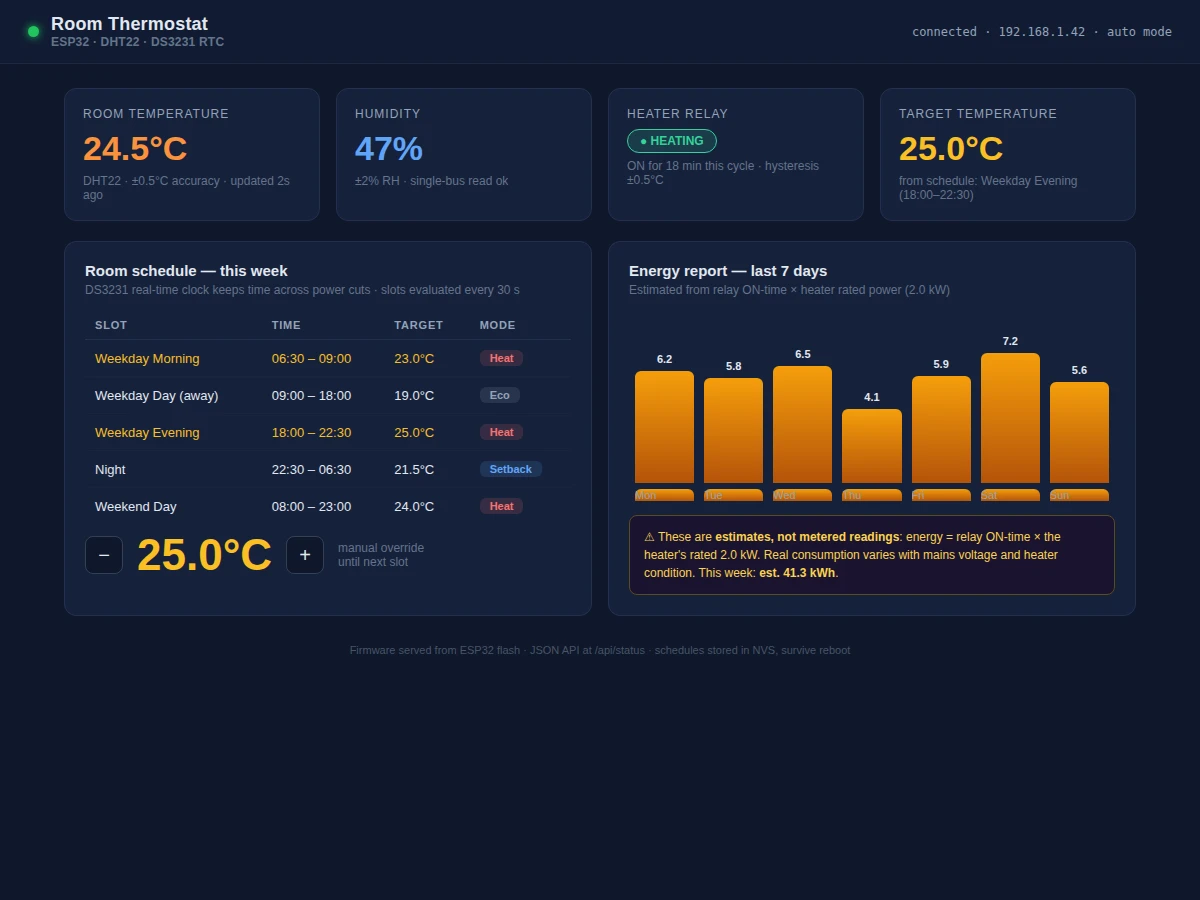
Most low-cost room heaters have two settings: on and off. They blast heat at full power whenever somebody flips the switch and keep blasting until somebody remembers to turn them off again — at 3 a.m., in an empty room, at the same intensity as a cold evening. The waste is invisible, so nobody acts on it. This project fixes that with a thermostat built from an ESP32, a DHT22 temperature-humidity sensor, a DS3231 real-time clock and a relay module: the controller reads the room every two seconds, follows a weekly schedule of target temperatures set through its own web dashboard, and switches the heater only when the room actually needs heat. Because the ESP32 hosts the dashboard itself, there is no cloud account, no subscription and no phone app to install — any device on the same Wi-Fi network gets live readings, schedule editing and a weekly energy report. The DS3231 keeps time through power cuts, so a midnight outage does not wipe the schedule.
Reads temperature and humidity every 2 seconds and hands calibrated digital values to the ESP32 over a single data wire.
Follow the working sequence
How it works
- The DHT22 reads temperature and humidity every 2 seconds (its rated sampling period) and hands calibrated digital values to the ESP32 over a single data wire.
- The firmware reads the time from the DS3231 over I2C, looks up which schedule slot is active, and pulls that slot's target temperature.
- It compares the measured temperature against the target with a ±0.5 °C hysteresis band and drives the relay GPIO accordingly — ON below target minus band, OFF above target plus band.
- Each second the relay stays ON is added to an energy accumulator; kWh is computed as ON-hours multiplied by the heater's rated power (2.0 kW design value).
- The ESP32's web server serves the dashboard and a /api/status endpoint; schedule edits from the page are written to non-volatile storage and take effect immediately.
- On power loss, the DS3231's coin cell keeps the clock; on reboot the ESP32 reloads the stored schedule and resumes control within seconds.
Tech stack:
- ESP32 DevKit V1 (Arduino framework)
- DHT22 temperature-humidity sensor (single-wire)
- DS3231 real-time clock (I2C, battery-backed)
- Single-channel relay module
- 0.96-inch I2C OLED (SSD1306)
- HTML/CSS/JavaScript dashboard served from ESP32 flash
- JSON REST-style API endpoints
| Parameter | Value |
|---|---|
| Temperature sensor | DHT22: −40 to 80 °C range, ±0.5 °C accuracy (datasheet) |
| Sampling interval | 2 s (DHT22 rated maximum rate) |
| Schedule engine | Weekly timetable, slot evaluated every 30 s |
| RTC accuracy | ±2 ppm, 0 to 40 °C (DS3231 datasheet), battery-backed |
| Control method | Relay on/off with ±0.5 °C hysteresis |
| Relay contacts | 10 A at 250 V AC (expected — verify against heater load) |
| Dashboard | Served from ESP32 flash; reachable on the same Wi-Fi network |
| Energy reporting | Relay ON-time × heater rated power (2.0 kW design value); estimate, not metered |
| Local display | 0.96-inch OLED over I2C |
Project features
- [Weekly room scheduling] Set different target temperatures for morning, daytime, evening and night slots on weekdays and weekends; the firmware evaluates the active slot every 30 seconds and drives the relay through ±0.5 °C hysteresis.
- [Web dashboard hosted on the ESP32] Live temperature, humidity, relay state, target and a schedule editor in one page served straight from the microcontroller, with JSON API endpoints for status and schedule changes.
- [Honest energy estimates] The dashboard multiplies relay ON-time by the heater's rated power to show daily and weekly kWh; every figure is labelled an estimate, never presented as metered consumption.
- [DS3231 real-time clock with battery backup] Schedules keep running through power cuts; ±2 ppm accuracy (0 to 40 °C, per datasheet) means negligible drift over a semester.
- [Local OLED readout] The 0.96-inch display mirrors current temperature, target and relay state on the prototype itself.
- [Manual override] Nudge the target up or down from the dashboard; the override holds until the next schedule slot begins.
- [Hysteresis control] A ±0.5 °C deadband around the target stops the relay chattering near the setpoint, extending relay and heater life.
What is included
- Assembled thermostat prototype (ESP32, DHT22, DS3231, relay, OLED on breadboard)
- Complete firmware source with schedule engine, web server and JSON API
- ESP32-hosted web dashboard (single-page layout for desktop and mobile browsers)
- Wiring diagram and assembly photos
- DHT22 calibration notes (offset check against a reference thermometer)
- Project report PDF (background, design, methodology, results)
- PPT presentation for final review
- Viva Q&A preparation document
Limitations & prerequisites
- The energy report is an estimate (relay ON-time × rated heater power), not measured metering — real consumption differs with mains voltage, heater condition and room factors.
- The DHT22 reads at most every 2 seconds and is accurate to ±0.5 °C; room regulation is realistically about ±1 °C depending on thermal mass.
- A 10 A relay limits the heater to roughly 2 kW at 230 V; larger heaters need a contactor, which is outside this build.
- The dashboard is reachable only on the same Wi-Fi network — there is no cloud access and no phone app.
- Schedules survive reboots, but the heater itself is mains-powered: a power cut still means no heat until supply returns.
- This is a room-comfort thermostat, not a certified heating controller — unsuitable for safety-critical or unattended high-load installations.
Frequently Asked Questions
How does the thermostat know when to switch the heater?
The ESP32 checks the DS3231 clock every 30 seconds, finds the active schedule slot and reads the room temperature from the DHT22. If the room is more than 0.5 °C below the slot's target, the relay switches the heater on; once it crosses 0.5 °C above, the relay drops. That hysteresis band prevents the relay from chattering near the setpoint.
Is the energy report a real measurement?
No — and the dashboard says so plainly. The ESP32 counts every second the relay is ON and multiplies by the heater's rated power (2.0 kW) to estimate kWh. That is accurate enough to compare schedules and see the cost of comfort settings, but it is not metered consumption: mains voltage, heater condition and room factors all shift the real figure.
What survives a power cut?
Time and schedules. The DS3231's coin-cell backup keeps the clock running, and the weekly timetable lives in the ESP32's non-volatile storage, so the thermostat resumes the correct slot within seconds of reboot. The heater itself, of course, needs mains power — the thermostat cannot heat through an outage.
Do I need the cloud or an app to use it?
No. The ESP32 hosts the entire dashboard itself, so any phone or laptop on the same Wi-Fi network can open it in a browser — live readings, schedule editing, manual override and energy reports. Nothing leaves your network and there is nothing to subscribe to, which also means no remote access from outside the house.
Is this project suitable for a final-year project?
Yes — for Electronics, Electrical, Instrumentation and IoT programs. It combines sensor interfacing, real-time scheduling with battery-backed time, mains switching through a relay with hysteresis, and a web interface hosted on the microcontroller itself. The honest energy-estimate-versus-measurement discussion gives the viva examiner something substantive to probe.
Components & software requirements
- ESP32 DevKit V1 (Arduino framework)
- DHT22 temperature-humidity sensor (single-wire)
- DS3231 real-time clock (I2C, battery-backed)
- Single-channel relay module
- 0.96-inch I2C OLED (SSD1306)
- HTML/CSS/JavaScript dashboard served from ESP32 flash
- JSON REST-style API endpoints
Delivery information
Built-to-order project. Delivery timeline is shared after order confirmation based on current queue.
Support terms
Complete documentation, setup guide, and viva preparation included. Support for setup and explanation provided.
Download free synopsis (PDF)
Enter your name and email — the synopsis PDF downloads immediately. We may send occasional project updates; no spam, unsubscribe anytime.